Saturday, March 14, 2009

Quad 606 Transformer Swap

François' (Besancon, France) Quad 606-1 started making a rumbling sound....


Some QUAD 606 MK1's start to make a rumbling sound after some years - from the amplifier itself, not through the speakers.


This means that the transformer is worn out and needs replacement (we know the same problem from the Quad 405 where we can replace the old transformer with a Toroïdal version).


The problem with the 606-1 is that a 400VA 2x 80V Toroïdal transformer won't fit as the diameter is much too large. Quad uses a Toroidal transformer in the 606 MK2, the 707 and the 909 but they developed a special PCB for it that wont fit the 606-1 chassis.


The only alternative seemed to order a "New Old Stock" "classic" replacement transformer for the 606-1 but this appeared to be very expensive and we don't like the quality of this transformer neither.


So we thought about using 2x 250VA 2x 40V Toroïdal transformers. This offers the advantages of extra power headroom (500 instead of 400VA), (even) better channel-separation as we use two different transformers and the possibility to use larger PSU capacitors.


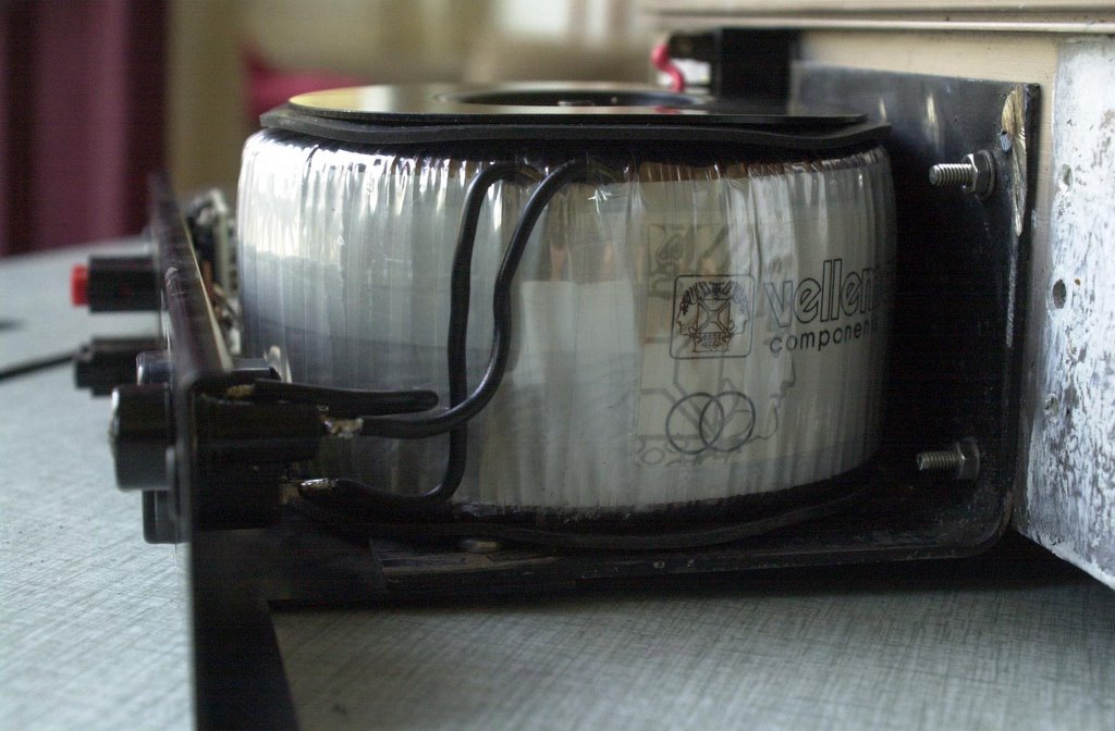
We decided to use 2 Noratel 250VA 2x 40 Volt transformers. They are 50mm high and 120mm diameter.


But how to build them into the Chassis? Chris Devrieze has been puzzling with the question during several days and came up with a very good solution.
  • We remove a part of the old transformer mounting-frame on the bottom of the (upside-down) chassis so the new transformers will fit in between

  • As we can't mount the capacitors and the diode's on top of the transformers anymore - there is no space - we glue them with 2-component Epoxy on both sides of the transformers

  • Both 115V primary windings are soldered in series (for Europe) or in parallel (for the USA & Canada) and the secondary windings are soldered in series to obtain 80V

  • We drill a hole in the top cover-plate and we use a M6 x 120mm screw to fix both transformers to it after connecting all the wires. We put 4 rubber feet on the bottom to avoid all movement of the transformers once they are fixed

  • We mount the cover-plate with both transformers to the chassis with M5 x 40mm screws in the four corners

Of course we also did a full revision of the amplifier-boards to bring the 606 to a Quad 909 level and we replaced the connectors.

Click on the pictures to enlarge.

Dada Electronics will offer the 606-1 transformer swap as an option to the 606 revision service and will sell the Noratel 250VA transformers in the Ebay-shop.

Any questions? Info@dadaelectronics.com

Stefaan, Chris

Wednesday, November 16, 2005

Quad 405 Tansformer rumble ....


Some older 405's have a problem with the transformer. It produces a rumble (not in the speakers but in the transformer itself).

There is no way to fix this problem except by replacing the transformer.

Of course you can order a new transformer from Quad but this is a quite expensive solution. Therefor this alternative: one can fit a toroidal transformer (300VA 2x 35V). This also offers the advantage of better stability and somewhat less noise, limiting the cost to about 90 Euro.

The only problem: to fit it in you will need a special mounting plate. I found one on Ebay in the UK, Stuart Adamson had them made by a steel manufacturer. I also had to move the fuse because it was in the way (see the picture).

But now my 405 works fine again ;-)

PS. The transformer you need is a Toroidal 2x 35 or 2x 36 Volt, 300 VA (not less!). Make sure it will fit in.

Stefaan

A 300VA toroïdal transformer and the mounting-plate are now available in the Dada Electronics Webshop.

Friday, September 03, 2010

Upgrading and Monoblocking a pair of 520f amplifiers.

By Stefan Vertongen, Belgium.

Description of the amplifiers, as bought on the second hand market:

-Serial number: 005 095; one amp board with power transistors MJ15003, the other with MJ15024; furthermore capacitor C9 and C11 were not foreseen by factory , drivers “40872 – no brand”
-Serial number: 005 097, original power transistors RCA 17556, drivers RCA40872
Both of them had power amp boards 12828/7 (not the later -8), the original power-supply elco’s, XLR inputs and LS outputs; there were no output limiters or input transformers; XLR pins 1 and 3 were bridged. In fairly mint state, with scratches; used in a tennis club during 20 years, but apparently no heavy use (no blackened components).

General (my) philosophy:

- Some people prefer to keep everything in ‘original’ state (in order to keep a decent market price for the private museum lovers), and/or only repair what is faulty; to the contrary, I have a tendency to upgrade components/circuit whenever it will have a positive impact on overall sound quality, and will change even the ‘look’ if it improves technical functionalities (also, it gives a personal exclusive touch!).

- The conversion to mono-blocking was in my configuration mandatory: I use one power amplifier for one loudspeaker; the challenge was to see if those Quads would be competitive with the legendary Studer A68’s or ACCUPHASE M100…

- I am a music/audio-lover, not a qualified technician (with some basic technical knowledge acquired during the years); so, many thanks to the prompt, no nonsense advices of Stefaan (by the way, he also sells the components !) and Joost from DaDa Electronics, and especially Louis (audio technician of Microware Solutions workshop in Dendermonde, disposing of a scope and frequency generator); I am sure, especially for the latter, that it wasn’t always easy to satisfy all my inquiries, indeed “paradise” –not even the technical- isn’t to be easily found on earth !!

- Never underestimate the complexity of things; Mister Peter Walker’s principle ‘Keep it simple’ was not always followed up by his production people !(different boards, omissions, many versions/changes in the 500 Series); by the way, this project was a piece of cake compared to the revision of the integrated ‘MARANTZ PM94’…don’t even think buying this nightmare !!

The upgrading of the amplifiers

First of all: I applied strictly the content of Joost’s blog (just go to the blog ‘520f’, nice pictures). Very clear on ‘what to do’ issues, except details for mono conversion. This was our main reference.

Additional:


- I removed the existing XLR LS connections – what an unpractical connection!- and replaced by WBT looking terminals. Of course, the old oxidized input XLR is replaced by a new Neutrik.

- A SOWTER 3575 input transformer was installed (in order to match the incoming balanced line from my preamplifier to an asymmetrical signal; although Joost didn’t like the idea, I installed after the transformer a cinch (RCA) connector (flexible use in other audio installations); a switch to isolate the transformer in the circuit was necessary: if not, a square wave of 30 Hz input signal looks awful because the RCA input line is somewhat influenced by the transformer…NB: this transformer was optionally installed by Quad in the eighties and is still produced.

- Substitution of the power transistors MJ15024 by MJ15003 for conformity.

- Replacement of internal signal cabling by a multi-wired core, shield, both Teflon insulated; they are not very flexible, nor easily stripped.

- Replacement of all small 0.1 ohm resistors R32 (one of them was faulty; the rest didn’t ‘look’ in good shape, metal film 1% on all power-amp boards.

- Original opamp: Stefaan is right, although recommended by several discussions on websites, a replacement of the original isn’t necessary (because NOT in the signal path)

- Mono conversion: look at the components that Stefaan added to the blog of Joost; as the potmeter in the Quads aren’t sufficiently accurate for ‘trimming’ the output voltage between the two channels, a dedicated 5Kohm was installed and one of the original was put on retirement. Now, this resulted in an acceptable imbalance of about 20 mV between the power-outputs. Placement of the 2 loudspeaker connections, with Dale resistors.

Some measurements: (input of 230 Volt mains with a variac):

- Peak to peak voltage of about 90 Volt, resulting in a 32 Volt RMS or about 130 Watt (before clipping) power on a LS load of 8 ohm. The old RCA transistors gave even a couple of volts more!
- On a power supply board, an imbalance between H+ and H- of some volts: 51/54 Volt with no load (don’t worry says Stefaan…); the other unit approached the total 110 Volt of supply voltage.
- Very nice scope analysis of 15 kHz and 30 Hz sinus signals.

- The volume-potmeter indicator was somewhat calibrated to the notional ‘0db inscription’ with a signal of 1 kHz / 0,775 V and ‘just’ before clipping.

- On one of the mono-amplifiers I had an audible (ear against loudspeaker; nothing at 0,5 meter distance) hum…Spent a lot of time on efforts to cure it… a headache (not the elco’s but: mains transformer, input transformer, cabling, earth loop, ??!). Finally, back to the basics: I found the bad guy, the R40 was burnt!! Replaced with 1 watt dissipation type.
Nb you’ll find on diy websites many complaints about ‘noise’ from these amplifiers; they refer mostly to the standard xlr connector, where you have to connect the pins ‘earth’ and ‘cold’ signal ,with an asymmetrical signal input.

-Some further possibilities:

*This is a Professional amplifier, but surprisingly without a ‘standard’ overload or ‘clipping’ indicator. An omission, Mister Walker? I found a reliable circuit description – look at http://sound.westhost.com/project23.htm - based on a drop in the supply voltage when reaching high output levels. I think that Joost won’t like this ‘rape’ of the 520 front… I still hesitate, but I use to run high output levels and my preamplifier can deliver much more than 1 volt on dynamic cd’s! Beware: “clipping” is a complex subject!!

* Driver replacement by MJE 15031(don’t expect huge improvements)

Now, how does it sound?? "The proof of the pudding is in the eating"

After ten hours of listening: no disappointment. YES,.. they sound very dynamic, neutral, punch, very good lower bass, monitor like…’richer in details’ than my modified 405 II, perhaps lacking a bit the ‘velvet’ sound on voices/piano.
I keep them, for sure….together with Studer and Accuphase! Worthwhile!!!
Nb listening on loudspeakers Tannoy Kensington, alternate : Sonus Faber Amati (both of them very ‘musical’).

Stefan Vertongen


Comments by Joost: DaDa Electronics

First of all: we are very pleased with customers like Stefan. They try something different and are willing to share there experience with us and other Quad-fans.

The 520 has no voltage output limiter or indicator, that is correct but it is safegaurded by a strict current limiter and a thermal protection. Which simply swithes of the amplifier when it gets too hot.

Stefan mentioned "Pro" use and the omission of a clipping indicator. In most cases the power amp in pro use is out of sight, on stage with the loadspeakers, while the mixing desk is in the public area. So: set the levels right and use the clipping indicator on the mixing desk.

I will make a separate article about the monoblocking issues and the extra resistors needed.

I don't like input transformers, if you can avoid them: do it. But in the setting of Stefan they are needed. Quad used the Sowter's but replaced them by there own opamp-based input modules in later versions.

I keep the equipment as orignal as possible, but I understand the pragmatism behind Stefan's conversions.

Joost

Friday, March 23, 2007

The Quad 50E revision, including 50D info

(click on the picture to enlarge)
The 50E has been produced from 1966 to 1983. The quantity that was sold counts up to 12.000. Although it shares the looks of a 303 it is a different amplifier.

The 303 was built from 1967 to 1985, numbers produced: 94.000. I own a early and a late version of the 50E, the only difference is the fuse holder! Internally there are more things that were changed during the production run. The early type has its own heat sink, the later version shares its heat sink with the 303.

Of course components differ during their lifetime, but as far as I known there are no modifications or what's so ever. Quad added a heat sink to the voltage regulator transistor, and that's it.

So the 50E is not a better version of the 303, in fact it's a pity Quad didn't develop a 50E with the famous Triplet output configuration.
The 50E has a regulated power supply for the driver stages and a well filtered supply for the output stages. A choke is very good in deleting HF rubbish. It is a technique from the tube era. The 50E will give 50W into almost any load, but not at the same time! In fact the power bandwidth concerning loads is relative small, it uses an output transformer instead of an output capacitor like the 303.

It is idiot proof though, it is funny, for professionals you design an idiot proof amplifier, for normal people.........well. There is an optional 600 ohm balanced input transformer. There also is an input potentiometer to cope with large voltage, 1966, input signals.

The first thing you should do when you buy vintage audio equipment, is to collect information about it. Never connect it to the mains supply in the first place, in most cases there will be an expensive noise! Start by cleaning the unit, 40 years of dust-collection will cause problems. As Quad used standard components, replacing the electrolytics and trimmer pots is easy. Check for suspect looking solder joints as well in the first place.

It's a pity the replacement capacitor for the power supply looks a little lost in the engine bay, although it is supposed to be twice the capacity. That should be a progress! I used a NOS, New Old Stock, capacitor from BC, with a projected life of 200000 hours. It appears to fit between the original brackets. I use a Hameg component tester to check the components within the circuit. Once everything looks ok I connect the unit with a Variac to the mains supply. If this gives a good result, I connect the unit directly and I can start testing & adjusting.
First we set the Emitter voltage of Tr3 to 5.5 volts with trimmer Rv1, then the bias currents of Tr8 and Tr9. Instead of breaking the transformer links, we measure the voltage in R30 and R31. The bias current should be 30-40 mA. Some people think this is also the correct value for a 303, well it is not. This means the voltage across R30 or R31 is .5 x 30-40mA = 15-20mV. You will set this voltage with pot Rv2 and Rv3. Purists would say that I made a mistake. I forgot the base current of Tr8 and Tr9 flowing trough R30 and R31 indeed, but that does not really matter.

The output of a 50E consists of eight (4 x 17V and 4 x 8.5V)independend transformer outputs, you can combine these outputs in any way, as long as you keep Ohm's law in mind. Most people will use the 50E with the 17V output configuration. This means in fact six 17V windings in parallel. The 50D has a different output combination, it has only the four 25,5V windings (17V and 8,5v in series)! So compared to a 50E you will miss the important 17V (6 Ohm) option, you can rewire the 50D to this specification. In the 50D there is no option for placing an input transformer and the netsupply voltage must start at a minimum of 200V AC. Also the netconnector is an odd Cannon connector. The output connector is a 11 pin version of the 19 pin 50E connector.

An interesting feature occurs: biwiring!

You can connect four windings in parallel for the woofer and two in parallel for the tweeter section.
Because all the electrolytics are used for coupling or decoupling we can change (increase) the value of the caps without worrying about frequency problems. Because capacitors are a lot smaller, you can easily tenfold the value with the same outer dimensions. Sometimes I almost did.
Well, almost all the capacitors, C6 should stay 50uF, because it forms a high pass filter in combination with R10. By changing the value of R10, the gain can be adjusted. Increasing the value of R10 means reducing the overall gain of the amplifier.
This is far more preferable (lower noise) than reducing the input signal by the input pot meter on the front panel of the amplifier. Remember that the product of C6 and R10 should stay constant, when you change the value of R10, otherwise the low frequency behaviour of the amplifier will be changed.
So with Tr1 the gain is set, feedback is applied and the high pass filter is implemented, an combination we also find in later Quad designs.
The protection of the 50E (and 50D) is based on a current limiter circuit formed around Tr10. This circuit is triggered by two parameters: the current flowing trough the emitter resistors of Tr8 and Tr9 and the temperature of the heat sink sensed by R18.
The peak output can be increased by changing (increase) the value of R26 and R27. Remember that this amp was designed in the days of constant RMS output.
With modern speakers, peak power (and coping with low impedances) is very useful. The two output circuits are identical, that’s the advantage of using an output transformer with two primary windings.

Compatible Transistors, check pin layout!

BC109 BC184 BC451
BC154 BC560 BC214
BC142 2N3020
BC125 BC301-6
40411 MJ802
40408 BC142
IS922 1N4148
IS920 1N4003
AA129 none! 200mV reference diode

Joost


If you need a copy of the schematics or the 50e-manual send an e-mail to info@dadaelectronics.com

All Quad 50E and D electronic parts are available from Dada Electronics, send an e-mail to info@dadaelectronics.eu.


Sunday, December 07, 2008

Quad Power-supply design generations: pro & contra.

Second edited version 3 june 2010, thanks Peter!


Some thoughts about the design of the power supply in the 606 till 909 series.

Quad introduced a new power-supply in the 606 with an active earth circuit.


This basically means they removed the central earth wire from the transformer. As both power supply voltages now only depend on the value of the capacitors, an additional transistor-circuit was added to adjust the voltage across the two power supply capacitors.


If you used ‘matched’ capacitors, the extra circuit would not be necessary.


Looking at the simplified circuit diagram you will notice that it is impossible to have any DC current trough the loudspeaker. Quad introduced an elegant DC protection. The DC protection itself has nothing to do with the active earth, and without the transistor circuits, still there will be no DC current.


If one of the dumpers would fail the voltage over the capacitor will be doubled, hopefully the fuse will be blown before the capacitor does, as it is only rated 63V. Anyway, this is a far better solution than the Clamp circuit in the 405. From the DC point of view…

But is there a “Free lunch”?

If you compare the return current from the loudspeaker in a conventional setup, like the 405 (see the diagram), and the 606 supply, it looks like there is an extra power supply capacitor, a diode and half the secondary transformer winding in series with the loudspeaker in the case of the 606. This is worse than the output circuit of a 303!
Remember, the capacitors are of large capacity and the diode and the transformer winding are “behind” the capacitor. In the real world the loudspeaker current is delivered by the capacitors, they act as power supplies. Even in the situation were the centre connection of the transformer is used the current is supplied by the capacitors. There is only a small current through this wire, this is due to the tolerance in capacitors value. If the capacitors were matched, there is zero current in that wire. Check this with two power supplies in series and two resistors, the principle is the same. So in both setups the speaker current goes ‘’ through’’ the capacitors. In both setups the quality of the capacitors and the value are important. In the case of the Quad virtual earth the stability of the centre voltage is determent by the value (capacity) of the capacitors and the “speed” of the regulating transistor circuits.

Why this post?

In this paper I described two situations, the conventional earth wire and the 606 situation where the wire has an infinite resistance. Based on a idea of Keith Snook, what will happen when the wire is replaced by a resistor? If the value is low enough, the voltage on the power supply capacitors will stabilise, without the need of the extra transistor circuits. If the value is high enough the DC current will be limited.


The idea was to build a 405 PSU with the resistor and omit the DC protection. Until now I did not found a value that will match both the former criteria. The main reason for this is the fact that there is only very little time (5mS for the 50Hz situation, 60Hz is even worse in this aspect) for the capacitors to charge, the value of the resistor must be very low, but a low value wont protect your valuable speakers.


So until someone comes with a better idea, our own DC protection or the Quad implementations will still be needed.

Joost Plugge

DaDa Electronics

Tuesday, January 01, 2008

Quad 405 DIY illustrated guidelines - Step 1 to 3

This is the original 405-revision article published on this blog in 2006. We republish it on general demand.

Stefaan

I thought it was time to make an online step-by-step guide for upgrading a 405.

If you are in the US and you are looking for a DIY upgrade-kit, check out www.quad405.com. The guidelines remain the same but you won't have to pay more for low Dollar-rates and high shipment-costs ;-)

As I recently bought a very nice (but very old) 405-2 (thank you Leigh, I hope you had a good time in Antwerp) I will use this one as a photo-model. I will take pictures of everything I do and explain why I do it. All comments and tips are welcome of course.

The revision/upgrade will be a basic one without fancy or expensive things like the BB627, but I'll mention those options in the PS.

Click on the pictures to enlarge.

So here we go...

Step 1 - Getting the components together

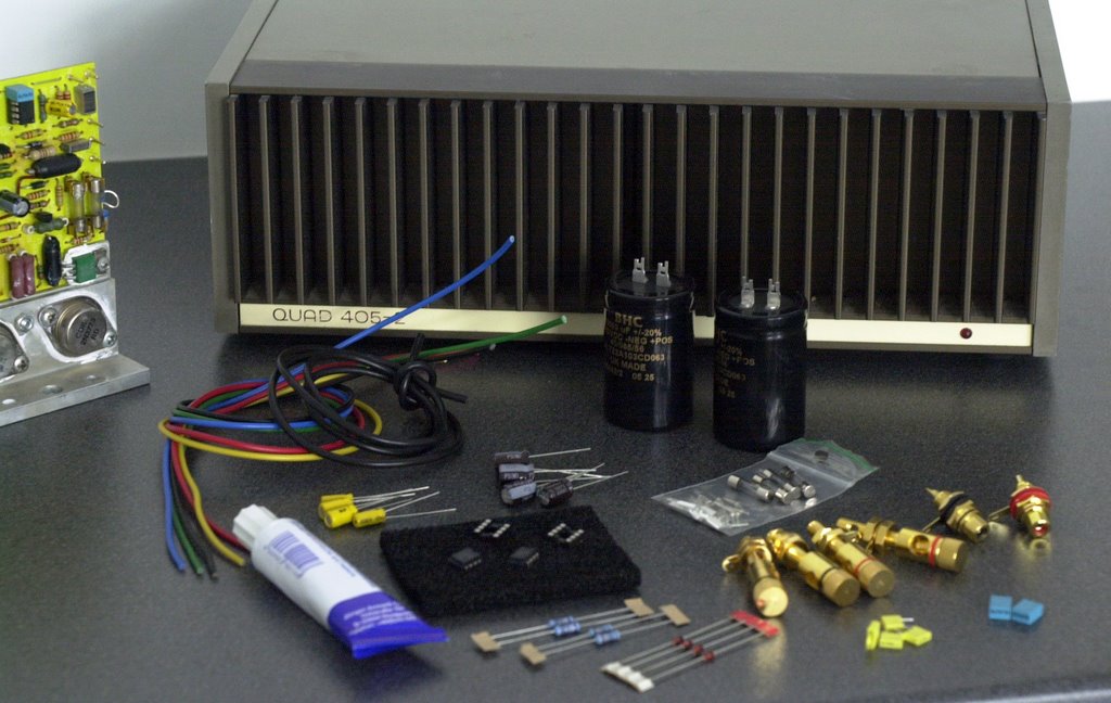
This may be the hardest part... Aspecially if you are looking for audio-grade components at an affordable price. The components I will use in this revision are:

BHC Aerovox 10.000 MF 63 Volt for the power-supply. These are quite expensive (+/- 16 Euro each) but in the power-rails we need the best quality. A less expensive alternative may be BC-components or Philips.
  • 100MF and 47MF 63V Audiograde capacitors for C5 & C10. In the 405-2 we will need 3 47MF per circuit-board.
  • Bipolar capacitors of 10MF (for the clamp-circuit) and 47MF (for the DC-feedback) x2
  • Metalfilm 1% 0,5W low-noise resistors for R2 and R6, and probably for R1, R3 and R4 as well (we'll come back to that).
  • Burr Brown OPA604AP-chips for the input-channel. We'll need 100NF caps to stabilise the power-supply of the chips and 16V zener-diodes to make the chip feel happy.
  • We'll also need some supplies like new fuses, IC-sockets, thermal compound, cables to replace the old cable-beam, LS & RCA connectors, PCB-connectors adl...
  • Last but not least: the schematic that corresponds with the exact serial-number. That won't be a broblem: send me an e-mail.
What equipment will we need?


  • The minimum is of course screwdrivers, pliers, soldering-equipment and a multimeter
  • Better would be a 2x50V lab power supply, a LF tone-generator and a 2 channel scope (but it is possible to do without them)
  • Ideal would be a low-distortion sinus-generator and a distortion-meter as well. I don't have those myself (yet) so don't worry;-)
Step 2 - Taking the 405 apart

The first step is to remove the top- bottom- and sidepanels. Sometimes, after 30 years, the screws are hard to remove. The best screwdriver to use is a Philips n°2 with a length of at least 20 cm.

We now understand why Quad made 4 hole's on the left- and the rightside of the backpanel: they were intended to facilitate manipulation of the screws of the circuit-boards.

I don't need to mention it's usefull to keep the screws apart. They can be replaced (they are M4 - which is a standard-size) but of course there is not much use in replacing the screws.

The best way to proceed is to remove the top-panel, then the bottom-panel and then the 2 side-panels.

The first impression of a newly opened 405 is usually a dusty one. This doesn't matter (in this stage ;-).

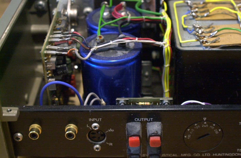
On the 405 on my table the voltage-selector is at 240 Volt. Switch it to 230 Volt. The connectors will have to be replaced (except the DIN-connector).

The LS-connectors were not only lousy in the first place, they are oxydated and will give a bad contact. The RCA-connectors are clearly worn. It's surprising there are any RCA-connectors, this is not standard. This amp has been modified.

The PCB-connectors have to be replaced anyway, they are oxydated and we will use new cabling.

I didn't spend time desoldering the cables, I cut them off. They will have to be replaced anyway.

The cable-beam of the 230V-side of the transformer should stay in place, there is no improvement in replacing it as there is only +/1 Amp max going through it. On the other side of the transformer we'll deal with up to 10 Amp.

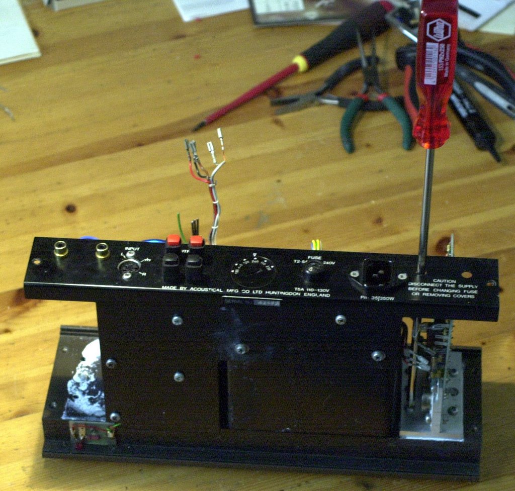
Something is very strange with this amplifier. The Serial number is 42472 and the amplifier boards are M12565:6. The earlier version of the M12565:5 was used from serial number 59001 on. It says "Quad 405-2" on the front panel (launched in 1983 and) it says "1977" on the transformer. One can always find the year of production stamped on the transformer.

This is a recomposed 405! It has 405-2 circuit boards in a 405-1 case. It also has 2 clamp-circuits (one on the 405-2 board and one on the LS-outputs like in the 405-1).

That's no problem, we'll throw away the 405-1 clamp-circuit and make this a great-sounding 405-2.

Step 3 - Fitting in the Power Supply capacitors and the connectors

We'll do this step first and we'll fit in the capacitors with transparent Silicone, so it can dry for 24 hours before we continue tomorrow.

As modern capacitors are a lot smaller (and better ;-) than the ones used 30 years ago we can either buy new fixing-rings to fit them in or use Silicone to fix them in the original rings. Another alternative is to wind some self-adhesive tape around the caps. This will work if the caps are not nuch smaller than the rings.
We'll mount the LS-outputs and the RCA-inputs before we fit in the capacitors. This makes working on the back-panel easier.

The mass LS-outputs do not have to be isolated from the chassis but the "hot" LS-outputs have to be isolated. The new RCA-inputs have to be isolated as well as in the 405 there is a difference between the input-mass and the output-mass.

The best order to mount everything is:

  1. The mass (black) LS-connectors with a (green) wire to the central mass-point on the frontpanel (this wire will be connected to the central mass-point later). We already put this wire in because it is easier to solder it when the capacitors are not in place. The mass LS-connectors don't need to be isolated from the chassis.
  2. The hot LS-connectors. Those need to be isolated from the chassis.
  3. The RCA-inputs. They are soldered to the L/R connectors of the 4-pin DIN-plug with normal wire.
  4. The capacitors. The wiring of the power-supply will be done later, after the Silicone has dried. Make sure to fit the first capacitor with the + on the left and the second one with the - on the left. The left-side will be our central 0Volt mass of the power supply.


Monday, August 07, 2006

Quad 33 Revision - Illustrated Guidelines

These are the step-by-step guidelines for upgrading the Quad 33 amplifier to modern high-end standards.

You can order the components from your local dealer or you can use the 33 upgrade-kit available via www.dadaelectronics.eu or via the Ebay webshop - Objectnumber 200014330586.


All resistances are Metalfilm low-noise 1% and all capacitors are Audio-grade (except in the power-supply) and 25 Volt or more.


Watch the polarity of all diodes & electrolyt capacitors!


If you need a (free) copy of the schematics or the service-manual, send an e-mail to info@dadaelectronics.eu
. You can also get 7/7 technical support about upgrading the 33 via this e-mail.

Step 1 - Modifying the power-supply from 11 to 16 Volt

Increasing the power-supply voltage to 16V makes the pre-amp more stable. The reason why Quad used an 11 Volt power-supply was the size of the capacitors at the time the 33 was designed.

We will also remove the 5V line on pin 4 of the output that was intended for switching on the power-amplifier but that was never used with the Quad power-amps.
  • Desolder the wire-beam and the mains-connections on the power-supply board. Remove the power-supply board (2 screws holding the transformer flanges). Remove all components except the transformer from the board.
  • Replace R500 and R501 with 27R resistances
  • Replace MR500 with a 1,3W 16 Zener
  • Replace MR501 & MR502 with 1N4004
  • Replace C500 & C501 with 4700MF. Mount them pretty flush so you can still access the screw hole in the transformer flange
  • Replace C502 with 1000MF axial
  • Remove R502, MR503, C503 & C504

  • Watch the polarities. The 3 diodes have the Katode (the black band) to the center of the board. C500 and C501 have the - on the topside and C502 has the + on the topside.
Step 2 - Changing the Balance-caps on the motherboard

Those 2 electrolyt caps are old and have dried out.
  • Replace C5 & C6 on the motherboard with 100MF
Step 3 - Upgrading the amplifier boards

We will reduce the sensitivity of the Radio 1 & Radio 2 inputs from 100mV to 250mV. This will allow for "modern" sources like CD-players to be connected without distortion and this will also improve the signal-to-noise ratio with another 6dB.

This is optional, if you only use Quad input-sources (and no CD-players ore sources with line-voltage) you could skip this step by not replacing R411/412.

Of course we will also replace all the old electrolyt-capacitors.

Repeat these steps for both amplifier-boards.
  • Replace C401 with 2,2MF
  • Replace C405 with 47MF
  • Replace C406 with 22MF
  • Replace R411 with 1K (optional)
  • Replace R412 with 1K2 (optional)
Step 4 - Upgrading the Phono preamplifier board

We have to change R300 to adapt the phono-preamp to the new power-supply voltage of 16V & we'll replace all electrolyt capacitors. R305 & R308 are replaced with 1% metalfilm for better stability.
  • Replace R300 with 1K5 to adapt the board to 16V power-supply)
  • Replace R305 & R308 with 82K
  • Replace C300,C303,C307,C308,C311 & C312 with 47MF
  • Replace C301 & C302 with 100MF
  • Replace C313 with 220MF (or 470MF)

  • Mount the capacitors fairly tight otherwise the board won't fit in the amplifier.
Step 5 - Adapting the Disc Adaptor Board

As we decreased the overall amplification we should increase the sensitivity of the Phono-input to stay around the same level.

Other combinations or the 4 resistances are possible to adapt the Disc-input to the PU-element.
  • Replace R105 & R106 with 560R
  • Replace R107 & R108 with 100R
Step 6 - Replacing resistances on the Tape Adaptor board

4 resistances on the Tape-adaptor board are replaced with Metalfilm resistances.

C202/203 are replaced with 2,2MF to improve the bass response and the phase coherence.
  • Replace R203, R204, R215 & R216 with 220K
  • Replace C202 and C203 with 2,2MF, the + side to the end of the board.
And... That's it!

Stefaan

Wednesday, May 03, 2006

Can you do a revision of my 405 FAQ's

How can I have my 405 making better music than a new one?


I often get e-mails from people asking "Can you do a full revision of my 405 (2)? How much would it cost? What exactly would you do? How much time does it take?" etc...

The answer is: yes, I can. It used to be a hobby but now I'm starting up a company, "DaDa Electronics", specialised in the revision and upgrade of vintage high-end Hifi.

How much would it cost?

One remark first: a big part of a revision is transportation-cost (forth and back). If you are in the US click www.quad405.com. If you are in Europe: keep on reading.

For a complete 405-revision I charge 145 Euro, everything included - except transportation costs.

What exactly is included in a complete revision?
  • All electrolytic capacitors (which dry out) are replaced by new ones
  • The power-supply capacitors are replaced with BC Components 10000 MF 63 V
  • The input-opamp is replaced with Burr Brown OPA604
  • The input-circuit is adapted to the new chip (power-supply of +/- 15 Volt, feedback)
  • The input-sensitivity is adapted to your pre-amplifier
  • The complete internal cabling is replaced with wire with better specs
  • The input/output connectors are replaced with high-quality gold-plated connectors, leaving the DIN-input in place, adding parallel RCA-inputs
  • Some capacitors are added to improve the quality of the power-rails, some resistances are replaced with metalfilm 1%.
  • The amp is measured and calibrated with professional lab-equipment
Do you use high-end audiophile components?

No, I don't. I use good quality standard components. If you want high-end components like Nichicon Black Gate 15000MF for the power-supply this can be discussed. In general the effect of "audiophile components" on the sound-quality will be minimal and the price will be high.

Do you replace the transistors?

It depends. In general transistors don't deteriorate like caps do. If they influence the sound quelity they might be replaced (like the power-transistors might be replaced with 2N3773 if necessary).

What if my 405 is broke?

It depends. If the reason is a bad connection, a broken fuse or a broken transistor, this is included in the revision. If the transformer or another essential component is broke it will have to be replaced at an extra cost.

How long does a revision take?


A full revision takes 2 weeks except if there are unforseen problems.

What are the options?

There are several options (see previous posts on this blog):
  • Adding the Velleman K4700 Loudspeaker-protection with power-on delay: 45 Euro
  • Replacing the transformer with a 300VA Toroidal transformer: 94 Euro
  • Burr Brown OPA 627 or 637 chips instead of OPA 604: 70 Euro
  • Changing the 405 to parallel Monoblock 125 Watt: 25 Euro
  • Changing the 405 to serial Monoblock 190 Watt: 95 Euro
  • Adding a symmetrical 0 Dbm input: 95 Euro
  • Having the Chassis professionaly repainted: ask for a quotation
Is there a warrantee?

Yes, there is a 6 month full warranty after the revision. It excludes damage due to transportation or misuse but it includes the complete amplifier, not only the replaced components.


Can you do a revision for other Quad's?

Indeed. I am specialised in revisions for Quads between the 33 and the 606, the vintage B&O receivers and the Revox taperecorder A77.

How to proceed?

Send me an e-mail (verdonckt.stefaan@skynet.be) describing the 405. Adding a picture of the inside and describing the pre-amp and the speakers it is used with is very usefull.

To send it to my address (in Antwerp, Belgium) you could remove the top- bottom- and side-covers to reduce weight and transportation-costs. Make sure it is well-packed.

Stefaan


Tuesday, January 31, 2006

Quadrevision Live: The Quad/Rogers 405 studio monitor


A very interesting amplifier has fallen into my hands!

Quad used to make OEM amps for the BBC, as studio monitors.

Quad worked together with Rogers, which made an active 2-channel filter with symmetric .650 V inputs and the loudspeakers that go with it.

The left channel of the 405 is used for the high tones, the right channel for the bass-tones .

The tweeter-channel is limited with the voltage-limiter originally intended by Quad for connecting the ESL speakers. Nice ;-)

Specific Neutrik-cables were designed for the set to connect the speakers and to connect the inputs to a symmetric pre-amp or mixing-table.

Revision step 1: Making a phase-shifter

As the input is a symmetric one we'll have to make a phase-shifter in order to connect the signal-generator in a symmetric way to the filter for measuring-reasons. With a breadboard and a single transistor this can be done in 5 minutes.


Now we are ready to measure the filter and check the bandwidth of both low and high channels on the scope. We will use a 1 KhZ .650 Volt sinus to start with.

But first we'll have to replace the old capacitors on the filter-board. Rogers used Tantalum capacitors that are awful for audio-applications but I guess they were fashionable in the 7-ties %-)

I'll take my bike and go to the electronics-shop. See you later.

In the meantime you should also take a look @ http://www.mhennessy1.f9.co.uk/rogers/ls58.htm

Revision Step 2: Checking the Filters

Revising and upgrading the 405-modules was straightforward, as I did about 100 of them before. Both amps (you have one per Rogers 5/8 speaker of course) have been made with +/- 4 years difference (1979 and 1982).

I think this is normal, the BBC ordered several hunderds of them from Quad/Rogers for on-the-road usage and stored them in the same warehouse. We can not expect similar pairs to stay together.

We are looking @ 2 405's with totally different Rogers-filters inside. Since 1982 Rogers removed the "Bass boost" option and simplified the schematic. The newer filter shows a strong distortion due to the input-transformer, which was to transform the symmetrical input to a non-symmetrical signal for the filter.

The Rogers-filters were built with transistors and very old components and there are no schematics to be found...

Revision Step 3: giving up the project...

There were many reasons why Jean-Marie and myself were very unhappy with the Rogers crossover filters.

Rogers used a small transformer to change the balanced input-signal to unbalanced in the input-line. Although this transformer does the job it causes a lot of distortion and phase-shifting.

The filter is made with transistors and some very old components, some of which were broke. The schematics can't be found.

So we decided to remove the filters, upgrade the Quad's and use a Behringer active filter instead.

Jean-Marie bought one for only 100 Euro. New, with a 2 year warranty. We'll connect it next week and we'll keep you posted...

What Peter Walker said about active crossovers (In an interview with Adio Amateur, 1978):

"AA: Some people like splitting up the signal with electronic crossovers, Do you see problems in that?

PW: It would cost more money! Provided you're not overloading, there are no advantages. If you've got three amplifiers covering three ranges, then you can run into overload with less trouble, because the bass can overload and it won't inter modulate the high. Therefore we can get away with more distortion audibly successfully. If you're saying that an amplifier should never run into clipping, then using three amplifiers is no better than one amplifier. One amplifier with three times the power would be rather better, because at least the power can come in any part of the frequency range. So a hundred Watt amplifier covering the lot would be better than three 30 Watt amplifiers, middle, bass, and treble. Because if all the signal comes in the middle, which it can do, then you're only limited to 30 Watts - the other amplifiers are sitting idly by and you'd like them to come along to the middle one's aid, and they can't do that."

You can read the full article on The Audio Circuit (http://www.audiocircuit.com).

Stefaan

Monday, October 22, 2007

K4700 & Toroïdal transformer in the Quad 405


On general request: a picture of the Velleman K4700 and the 2x 36V 300VA Toroïdal transformer mounted in a Quad 405.


Several articles on both subjects have been published on this blog. You'll have to scroll down a long way....


Stefaan

Thursday, May 05, 2011

BHC Aerovox ALC10C instead of ALP22A in Quad 606-Mk2, 707 and 909


BHC recommends using the ALC10C capacitors instead of the older ALP22A in new developments. It is less expensive, smaller and it has better specifications. The ALP22A is still produced for replacements in older circuits (but is out of stock for the moment, new stock is announced for July 2011).


In the Quad 606-Mk2, 707 and 909 the ALC10C 15000µF 63V can be used but the pins won't fit the printed circuit board. This can be solved by cutting the two unconnected pins and drilling an extra hole 1,5mm) in the PC-board (see the picture).


Make sure to double-check the polarity, when the polarity is wrong the capacitors will be damaged. The - pin is beside the gold line on the side and it has a "-" sign on it. The + pin is the middle one of the 3 pins on the other side. The two pins beside it have to be cut.


Dada is developing an new Printed-circuit board with a 500 Watt Amplimo transformer and 4x BHC ALC10C 15000µF for replacing the transformer and the capacitors in a 606 Mk1, making it an Mk2.


The 15000µF 63V ALC10C can be bought in the Webshop here.


The (general) BHC Aerovox datasheet can be downloaded from our Website.


Stefaan

Wednesday, April 09, 2008

Installation instructions for the 405 Dual Mono Psu


This post explains the installation of the Dada / JPE dual mono power supply for the Quad 405 and 405-2, all models. The PSU and the tools are available in the Ebay Webshop.

Joost & Stefaan

Second introduction and important extra information

This dual mono power supply is a fully functional replacement of the original power supply, but it has a lower crosstalk figure as a result and the elco capacity is being doubled, giving a more stable power supply voltage. In a standard 405 the secondary windings of the transformer are combined to form a single supply. In post 405 amplifiers, like the 606 each channel has its own supply. There are two reasons for this new design. First it is necessary to support the more elaborate protection circuitry in the successors of the 405, second, it lowers the mutual interference of the two channels. By building the amplifier as a four pole device, the channel interference is at its minimum, because there is no common ground plane or wiring, it can/will also reduce earth loops in the feeding cabling systems.

Preparation and beware!

Start with a clean bench and the necessary tools. Although the Psu board is not very sensitive for static electricity, discharge yourself by placing your hands on the bare metal of the chassis before you touch the electronics. Or wear a special bracelet connected to the chassis. Read this instruction before you start working on the amplifier. If you power up the PSU without the amplifier modules, the voltage on the capacitors will be there for a long time! Discharge the elco’s with a bleeder resistance with a value of 1K. In the full floating setup the chassis is not connected to the signal earth anymore. For safety reasons the chassis must be connected to the wall socket or the pre-amp via a power chord with a proper earth connection!

Tools

· Philips (Posidriv) no 2 screwdriver
· Soldering iron, 25W, a soldering station with temperature control is the best
· Wire cutters and clippers
· A DC multimeter

Removing parts

For easy access: remove the top, bottom and side plates of the amplifier.
Remove the wiring from the capacitors and the rectifier bridge. Cut the wires where they are entering the cable beam. Remove the capacitors and the clips. Remove the Rectifier bridge. Remove all wires from the secondary windings of the transformer, leave the blank connecting wires in place on each secondary winding. Also remove the wires to the negative (black) speaker terminals.

Mounting the Psu in the chassis

Place the plastic self adhesive feet in the corresponding holes. Clean the area where the feet are to be placed with a solvent. Mount the board after the wires are soldered to the connecting pins, by removing the protective tape. and push the board firmly in position. You can always remove the board from the pins. Before final installation, test the placement procedure with the protective tape still in place.

Basic wiring

In this setup we only implement the power supply as a dual supply. The Din connector and the earth connection at that point will stay in place. For Quad 405-2’s with factory fitted cinch connectors: read the following paragraph. If you use additional cinch connectors, connect the signal ground to the earth point of the Din chassis part. Also reuse the earth connecting point at the location of the old rectifier bridge. Connect the wires as shown in the diagram. Start with the wires on the Psu, place the Psu in the chassis and connect the other wires. Also connect the two wires leading to the led on the two led pins on the Psu. Because there is already a series resistor on the Psu for the led, short circuit the resistor on the small Pcb underneath the amplifier. Or replace the resistor on the PSU by a wire link, and leave the resistor on the small Pcb underneath the amplifier in its original state. Both PSU’s have there own led connections, so if you wish you can connect a second led.

Building a floating amplifier, for the advanced DIY user!

To gain full benefit of the double supply, a more complicated route has to be followed. The chassis to earth connection on the Din connector should be removed. Also a new central "earth" point on each amplifier module is necessary. This is created by removing the centre screw on the heat sink, use a special transistor isolation washer (on the heatsink side) and a new bolt and nut, M3x15 (all from a TO220 transistor mounting kit) between the head or the nut (depending of the way the bolt is inserted) and the heat sink. Use a copper or steel washer on the PCB side to ensure a good contact. In this way we can connect wires to this point without making any contact with the heat sink and the chassis. Or solder the wires to the copper side of the module. For best results we only use the isolated cinch connectors and remove the wiring from the Din connector. If you have to use the facilities of the Din connector use the spare pin for a second signal earth connection.
In all Pcb's prior to M12565 issue 3 (serial number 1 to 50000) there is a serious layout problem, the signal (input) ground must be connected to the output ground, in this case our new created "earth" point, or R2 replaced by a wire bridge! See also the "Hum" post and comments.

Quad 405-2 with standard factory fitted cinch connectors. Serial 85000 and higher

Keith Snook mentioned high values of the DC offset on the speaker output terminals with late versions of the 405-2 with the standard isolated Cinch connectors. This problem is the result of the mixed use of signal earth and chassis earth to connect components on the Pcb. Between those two "earth" connections a resistor R2 with a value of 10 Ohm is placed. In the Quads with a Din connector those resistors are effectively short circuited by connecting the signal ground to the chassis. In the Quads with the cinch connectors R2 is not short circuited anymore, in real life, the problem Keith mentioned is smaller when you use a preamp with a common signal ground (as most of us do), the two R2 resistors of both channels are now in parallel, so the value is halved. But the two channels now have shared components, bad news for channel separation! The second action to be taken to minimize the problem: use a power cord to the 405 with an earth connection from the preamp. The voltage difference across R2 should be very low, only depending on the resistance of the wires of the cables. But if you want top performance, every detail counts! Why Quad did change the layout? In an all Quad system (34 or 44 connected to a 405), a hum loop can be introduced, depending on length and routing of the cables, because of the use of cinch cables and an earth connection, via the power cord from the preamp to the chassis of the 405. In the early DIN days the Power Amp was earthed via the signal cable, see also the connection between a 33 and a 303.

How does this relate to our double PSU? Basic or floating?

If you don’t experience any hum loops in your current system, in the basic wiring setup: connect the signal ground of the Cinch chassis parts to the chassis, as was the case with the Din connector. If there is a hum loop, solve this one in the power cord of the 405 by disconecting the earth wire at the 405 side. Is illegal in some countries! See the "Hum" post.

In floating mode, there are two solutions, first connect extra wires from the signal ground connection of the cinch chassis part of each channel to the new central earth point on the corresponding modules, in effect short circuit R2, or replace R2 by a wire link. The latter is the best and more elegant solution in my view. These solutions can also be aplied to the basic wiring setup, but it is not so basic anymore.

If a connection between the amplifier ground and the chassis is necessary, build it like Quad did in the 606. Use a separate 10 Ohm resistor with a small capacitor (4n7) in parallel to connect the Psu ground to the chassis.

Checks before and after switching on the amplifier

Connect the amplifier to the mains socket. On the red wire there should be 50V referring to the chassis or the module earth point. On the black wire there should be -50V. If you installed the Psu as a fully floating device, before switching on, check whit an ohm meter that there is no connection between one of the green wires and the chassis. Also check that there is no connection between the green wires of the two channels.

Appendix 1 Basic wiring
Appendix 2 Fully isolated wiring