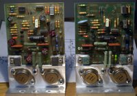
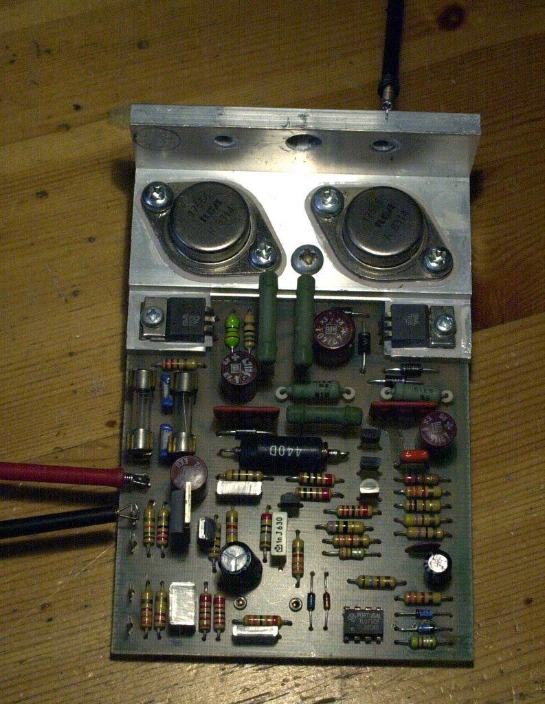
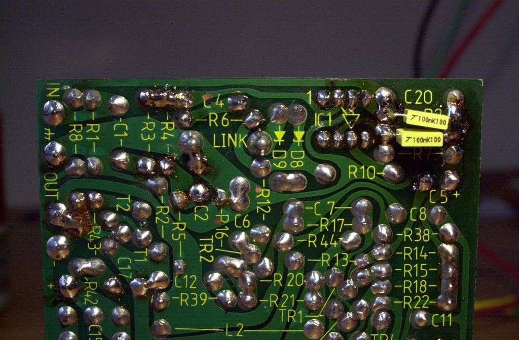
Wednesday, January 30, 2008

A 160W per channel Quad 303?


On Ebay such a beast is for sale, but what is it?


We get a lot of questions about this offering. Can you do that? Yes we can (maybe), but we won’t. See comments.


Can you also glue new capacitors on old ones, and leave corroded trimmerpot's in to place to maximise the profit? Do you also falsify graphs to proof your point? Yes we can, but we don’t.


The claimed 80W RMS in 8 Ohm is easy done, remove the regulated supply, ignore the fact why Quad did design this in the first place, and run the amp on an unregulated 90V supply voltage.


The second part, 160W RMS in 4 ohm is a lot more difficult, if possible. Our advice: check before you buy it, if the unit really deliver this kind of power. RMS, two channels, not peak-to-peak.

Why don’t we do this kind of work?

We work within the Quad design philosophy. We only upgrade and improve things if they really matter and are necessary because of modern speakers and sources.


If you need a 160W in 4 Ohm, buy a 520 series or a 606, 707 and 909. But remember, you need ten times the power to hear a sound at twice the original volume.

Joost Plugge

Friday, January 18, 2008

Who is behind Dada Electronics & the Blog?

We are guys in our 4-ties who have been working in informatics. Strange, isn't it? All 3 of us? Gregg joined us, he wasn't in informatics but in photography.


  • Stefaan Verdonckt (BE)


  • Joost Plugge (NL)


  • Esmond Pitt (AU)


  • Gregg Deking (US)


Labels:

Saturday, January 12, 2008

Quad 405-2 AC voltage considerations


From serial number 83000 and onwards Quad omitted the AC mains voltage selector on the Quad 405-2.
I recently checked such a late model Quad. It did not perform well. The power delivery was not on spec. On the outside of the unit there was a marking: 220V. But in real life the unit was wired for 240V. The Quad 405-1 had a selector with 6 positions, in the service documentation of the 405-2, only for four voltages is explained how to connect the wire links to the primary windings of the transformer. In the Netherlands the AC voltage is 230V, this is one of the missing voltages in the documentation, and the other is 130V. Because of the design, the DC power supply voltage of the amplifier is proportional to the AC mains voltage. So 130 V or 110 V does matter! To complete the documentation I drawn the missing link positions. You can also use these diagrams to rewire any Quad 405 and omit the voltage selector with those tiny wires. If you can hear a difference? I can’t tell you, judge for yourself. Before you rewire the amp, check the AC voltage during some weeks, check what is really coming out of the mains socket. Click on the diagram to get a fully detailed version, I also added some colour.

Joost Plugge

Labels: , , , ,

Wednesday, January 09, 2008

Gold - New DACT components available from Dada


Dada now has the DACT CT 2-50K-1, CT 3-5-4, CT 3-5-8 and CT 4-250K-2 in our stock.


Check out Dada's Ebay-shop.

Stefaan

Tuesday, January 01, 2008

Quad 405 DIY illustrated guidelines - Step 1 to 3

This is the original 405-revision article published on this blog in 2006. We republish it on general demand.

Stefaan

I thought it was time to make an online step-by-step guide for upgrading a 405.

If you are in the US and you are looking for a DIY upgrade-kit, check out www.quad405.com. The guidelines remain the same but you won't have to pay more for low Dollar-rates and high shipment-costs ;-)

As I recently bought a very nice (but very old) 405-2 (thank you Leigh, I hope you had a good time in Antwerp) I will use this one as a photo-model. I will take pictures of everything I do and explain why I do it. All comments and tips are welcome of course.

The revision/upgrade will be a basic one without fancy or expensive things like the BB627, but I'll mention those options in the PS.

Click on the pictures to enlarge.

So here we go...

Step 1 - Getting the components together

This may be the hardest part... Aspecially if you are looking for audio-grade components at an affordable price. The components I will use in this revision are:

BHC Aerovox 10.000 MF 63 Volt for the power-supply. These are quite expensive (+/- 16 Euro each) but in the power-rails we need the best quality. A less expensive alternative may be BC-components or Philips.
  • 100MF and 47MF 63V Audiograde capacitors for C5 & C10. In the 405-2 we will need 3 47MF per circuit-board.
  • Bipolar capacitors of 10MF (for the clamp-circuit) and 47MF (for the DC-feedback) x2
  • Metalfilm 1% 0,5W low-noise resistors for R2 and R6, and probably for R1, R3 and R4 as well (we'll come back to that).
  • Burr Brown OPA604AP-chips for the input-channel. We'll need 100NF caps to stabilise the power-supply of the chips and 16V zener-diodes to make the chip feel happy.
  • We'll also need some supplies like new fuses, IC-sockets, thermal compound, cables to replace the old cable-beam, LS & RCA connectors, PCB-connectors adl...
  • Last but not least: the schematic that corresponds with the exact serial-number. That won't be a broblem: send me an e-mail.
What equipment will we need?


  • The minimum is of course screwdrivers, pliers, soldering-equipment and a multimeter
  • Better would be a 2x50V lab power supply, a LF tone-generator and a 2 channel scope (but it is possible to do without them)
  • Ideal would be a low-distortion sinus-generator and a distortion-meter as well. I don't have those myself (yet) so don't worry;-)
Step 2 - Taking the 405 apart

The first step is to remove the top- bottom- and sidepanels. Sometimes, after 30 years, the screws are hard to remove. The best screwdriver to use is a Philips n°2 with a length of at least 20 cm.

We now understand why Quad made 4 hole's on the left- and the rightside of the backpanel: they were intended to facilitate manipulation of the screws of the circuit-boards.

I don't need to mention it's usefull to keep the screws apart. They can be replaced (they are M4 - which is a standard-size) but of course there is not much use in replacing the screws.

The best way to proceed is to remove the top-panel, then the bottom-panel and then the 2 side-panels.

The first impression of a newly opened 405 is usually a dusty one. This doesn't matter (in this stage ;-).

On the 405 on my table the voltage-selector is at 240 Volt. Switch it to 230 Volt. The connectors will have to be replaced (except the DIN-connector).

The LS-connectors were not only lousy in the first place, they are oxydated and will give a bad contact. The RCA-connectors are clearly worn. It's surprising there are any RCA-connectors, this is not standard. This amp has been modified.

The PCB-connectors have to be replaced anyway, they are oxydated and we will use new cabling.

I didn't spend time desoldering the cables, I cut them off. They will have to be replaced anyway.

The cable-beam of the 230V-side of the transformer should stay in place, there is no improvement in replacing it as there is only +/1 Amp max going through it. On the other side of the transformer we'll deal with up to 10 Amp.

Something is very strange with this amplifier. The Serial number is 42472 and the amplifier boards are M12565:6. The earlier version of the M12565:5 was used from serial number 59001 on. It says "Quad 405-2" on the front panel (launched in 1983 and) it says "1977" on the transformer. One can always find the year of production stamped on the transformer.

This is a recomposed 405! It has 405-2 circuit boards in a 405-1 case. It also has 2 clamp-circuits (one on the 405-2 board and one on the LS-outputs like in the 405-1).

That's no problem, we'll throw away the 405-1 clamp-circuit and make this a great-sounding 405-2.

Step 3 - Fitting in the Power Supply capacitors and the connectors

We'll do this step first and we'll fit in the capacitors with transparent Silicone, so it can dry for 24 hours before we continue tomorrow.

As modern capacitors are a lot smaller (and better ;-) than the ones used 30 years ago we can either buy new fixing-rings to fit them in or use Silicone to fix them in the original rings. Another alternative is to wind some self-adhesive tape around the caps. This will work if the caps are not nuch smaller than the rings.
We'll mount the LS-outputs and the RCA-inputs before we fit in the capacitors. This makes working on the back-panel easier.

The mass LS-outputs do not have to be isolated from the chassis but the "hot" LS-outputs have to be isolated. The new RCA-inputs have to be isolated as well as in the 405 there is a difference between the input-mass and the output-mass.

The best order to mount everything is:

  1. The mass (black) LS-connectors with a (green) wire to the central mass-point on the frontpanel (this wire will be connected to the central mass-point later). We already put this wire in because it is easier to solder it when the capacitors are not in place. The mass LS-connectors don't need to be isolated from the chassis.
  2. The hot LS-connectors. Those need to be isolated from the chassis.
  3. The RCA-inputs. They are soldered to the L/R connectors of the 4-pin DIN-plug with normal wire.
  4. The capacitors. The wiring of the power-supply will be done later, after the Silicone has dried. Make sure to fit the first capacitor with the + on the left and the second one with the - on the left. The left-side will be our central 0Volt mass of the power supply.


Quad 405 DIY illustrated guidelines - Step 4 to 6

Step 4 - Upgrading the circuit-boards.

The number of this circuit-board is M12565-6 (this is about the first 405-2 circuit-board). This means that the clamp-circuit is integrated on the board and that some improvements have been made about the current-limiting and the input circuit.

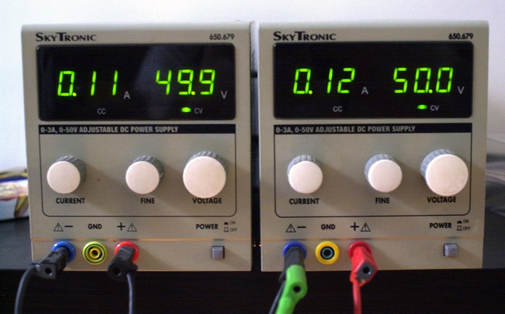
The first thing we'll do is connect it to a lab + & - 50 Volt power-supply to see what amount of power it eats. The - power-line should eat about 110 mA and the + power-line about 120 mA.

It passes the test well. This means the transistors are OK. (Zero Killed can be taken literally in this case). Both boards are OK.

The 0 Volt power-line has to be connected to the transistor-chassis. There is a 10R resistor between the input-circuit mass and the power-circuit mass. It will smoke if you are confused between masses.

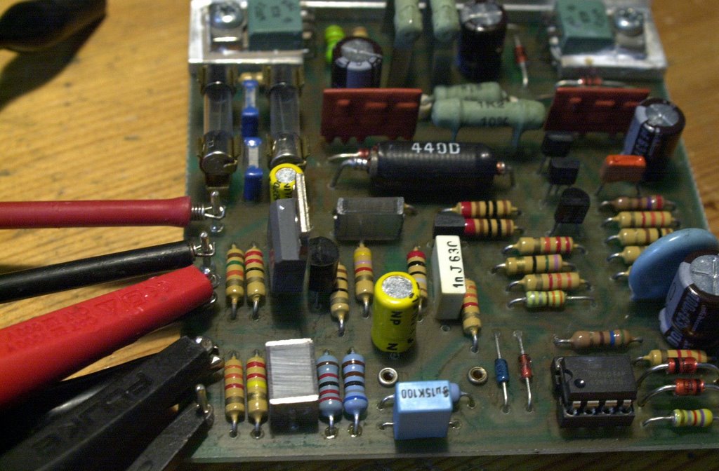
OK, we'll remove all components that have to be replaced. We won't touch the other board for the time being. This way we can always compare.

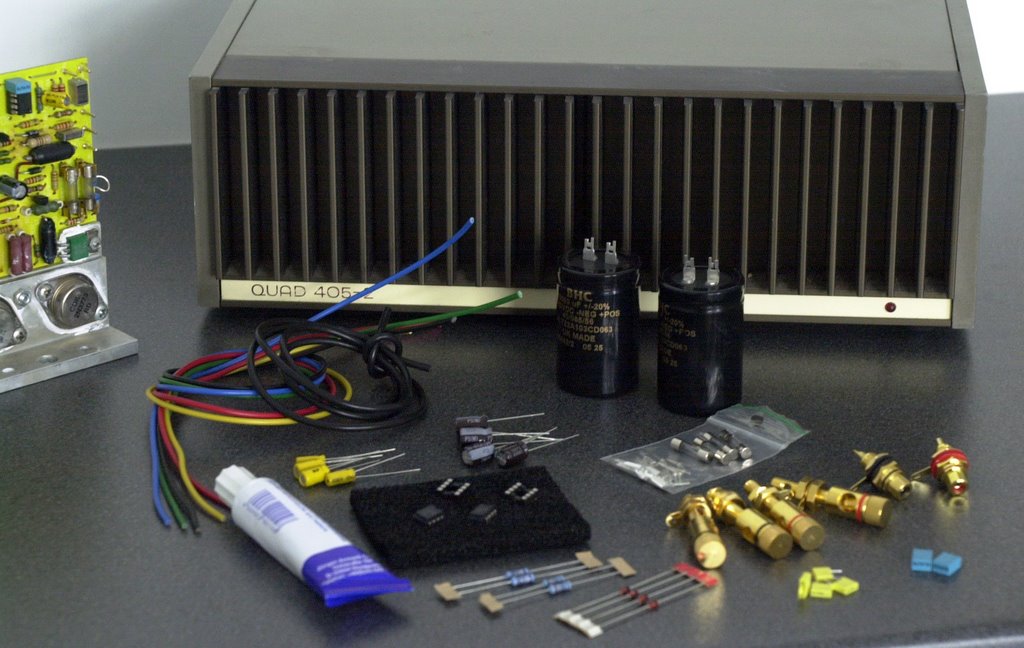
We'll replace R3 with 1% metal-film low noise 22K.

We'll replace D1 & D2 with 15V 1,3W.

We'll replace the electrolyts C4/C5/C18/C19 with new audio-grade caps.

We'll replace C2 and C10 with bipolar caps.

Of course we'll replace the opamp with BB604AP and the PCB connectors. The PCB-connectors have to be replaced because we have to redo the cabling. After more than 20 years they usually are oxydated anyway. We'll use 1,3mm silver-coated PCB-connectors here.

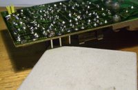
Soldering them to the PC Board is quite difficult as they tend to fall out and as they should be fixed very well in a horizontal way. I us a small carton box of 1 cm height to position them one by one.

We'll add 100 nF caps in the powerline of the chips on the backside of the PCB.

We'll also reduce the sensitivity of the input to 1,5V (from 0,5V). This will also reduce noise & distortion with another 10 dB.

We'll do this by increasing local feedback and DC feedback. We replace C4 with 150 nF MKT, R4 with 6K8 and R6 with 100K 1% metalfilm.

On this subject you should take a look at Bernd Ludwig's text and schematic (see the Quad-links in the left column).

Before adapting the second circuit-board we have to test the upgraded board to make sure it's OK. This way, if there is a problem, we can compare the voltages on both boards to locate the error.
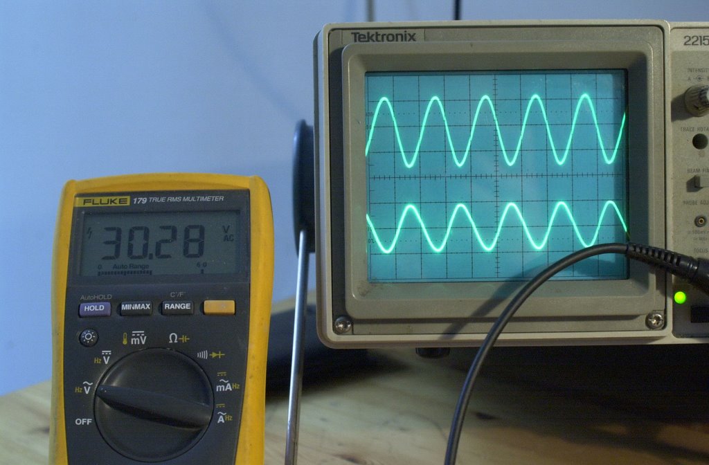
Step 5 - Testing the circuit-boards

When both boards are upgraded we'll connect them to a sinus-generator and to the scope. We'll connect + and - 50 Volt with our lab power-supply and connect a true-RMS multimeter to check the input- and output voltages.

Following measurements are OK:

- 0,01 Volt DC on the outputs
- 30 .. 32 Volt AC on the outputs before clipping. This corresponds with 110 .. 125 Watt into 8 Ohm.
- 1,7 Volt AC on the input before clipping. This corresponds with line-voltage for full power.

If you don't have all this lab-equipment, skip this step. We will make sure later that there is O VDC on the output and that the power-consumption in the power-lines is 120 .. 130 mA. In this case we'll do Step 6 first.

Step 6 - Cabling

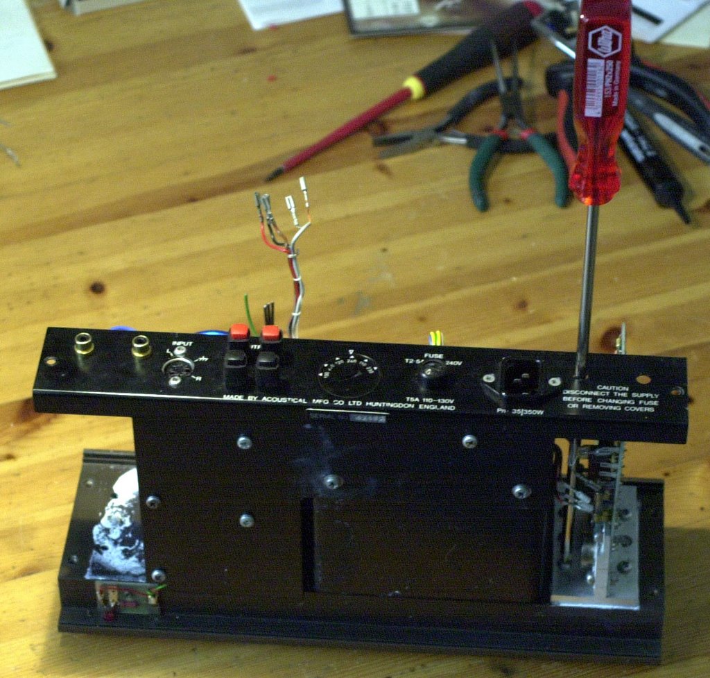
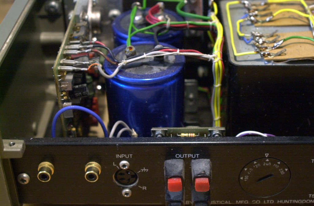
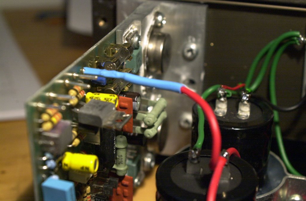
We start by cabling the power-supply. For internal cabling counts: the shorter the better. We'll use high-quality flexible 1,25 mm in 5 colors for everything except the 230 Volt lines.

We'll use following colors:
  • Yellow for AC power-lines (between the transformer and the bridge)
  • Red for the +50 Volt line
  • Black for the -50 Volt line
  • Green for the output-mass
  • Blue for the LS-output lines
We do all the cabling of the Power Supply lines and test the voltages first. They should be around + and - 51 .. 54 Volt DC. Before connecting the power re-check the polarity of the caps and the rectifier-bridge.

Don't forget to connect the mass-lines of the capacitors (one + to one - side of each cap) and the ground-line of the transformer to the central mass-point on the chassis.

It is better to twist all cables that have to be soldered to the same point together before tinning them, it makes soldering them a lot easier. Foresee cables to the boards as well.

Warning If the polarity of the caps is wrong they will explode!

Once the power-supply is OK, we fix in both boards adding thermal paste to ensure maximum heat-conduction with the chassis.

We can now connect the + and - power-lines to the boards (don't switch them or you'll kill the output-transistors!) as well as the LS-output cables to the red LS output-plugs.

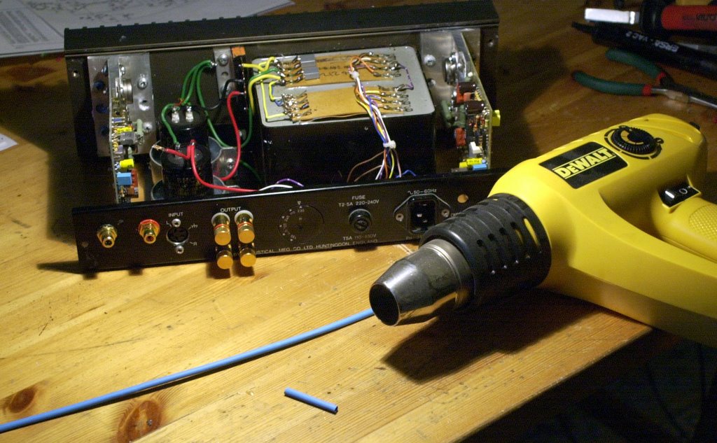
It is no luxury to use some Raychem (or other) Heat Shrinkable Tubing for insulating the +, - and output connections, as there are large voltages between them.

Before connecting mains-voltage we should check all cabling again with the Ohm-meter. We should alse re-check that each channel uses 120 .. 130 mA in the + and the - power-line and that there is less than 1 Volt DC on the outputs (typically 0,01 Volt).

If it passes these final tests we can now connect the speakers and the preamp and... enjoy the music ;-)

Stefaan