Wednesday, August 25, 2010

Measuring distortion with software


The case with the “Chinese” Quad 909 was the first occasion we worked with a software based distortion analyzer.

I used to work with a Sound Technology 1710A. The unit needs calibration and some repair; I have sent mails to ST, but no response until now. Just a calibration is a staggering 995 dollar or so, ex P&P, if they accept the work. Then I realized that even if they were willing to repair the unit, the performance will not be good enough to measure modern or modified vintage equipment. So we moved on.

Distortion analyzers like the ST are based on wideband AC RMS meters. First you measure the output signal of the amplifier under test, then you remove the test tone and measure the residue. Eventually you can calculate the distortion. This is off course distortion including noise.

The software distortion analyzers are based on a spectrum analyzer program and analog-to-digital and digital-to-analog converters. This type of analyzers measures the individual frequency components, the rest is “only” calculation!

Spectrum analyzers existed in the pre digital days, but they where very expensive.

The theory behind this is the fact that every repeating signal can be decomposed in so called harmonics and the basic frequency component. To measure amplifiers you also need a signal generator and an oscilloscope in (preferable) one software package. I started with a freeware solution from Sillanum Soft and the standard sound card in my PC. The results were very promising. The next phase was a high quality, 24 bit, 192 KHz sampling rate, low distortion, soundcard with balanced outputs (ESI Juli@). The results were more than ok. Because the Sillanum Soft package only has the basic functionality, I bought a package from Virtins Technology and built a proper brake out box with volume controls, a variety of connections and a possibility to connect load resistors and other lab equipment. To get more speed (calculation power) from the PC, I also installed a 64 bit operating system (dual boot option).

From the website of Audio Precision, a high end distortion analyzer manufacturer, I downloaded two very useful documents. The Audio Measurement Handbook and a large document titled "How to write and read audio specifications". By reading and digesting the last document you will find that most specifications of commercial audio equipment are not complete and meaningless in most cases! Even our Quad heroes wrote those kind of specs!

A practical case: measuring a Dada Electronics revised Quad 303

See the specifications in the picture. First I checked the distortion. Quad measured at a strange frequency of 700Hz. Also the term “unrestricted bandwidth” is undefined. What does ”up to 45 watt” mean in real terms of voltage and watts? My own settings: 1 KHz test signal, bandwidth: 20Hz to 20 KHz and 45 watt in 8 ohm loads, both channels driven and loaded. As you can see the specification of 0.03% is easily met. If you remove or lower the load the result is spectacular. Very low distortion indeed.

The next measurement was the crosstalk. Quad did not specify the output parameters. As you can see, with the channels loaded with 8 ohm and the power at 45 watts, the channel separation is below modern standards. Only good enough for vinyl replay or FM broadcasts. If you remove or decrease the load, it is ok.
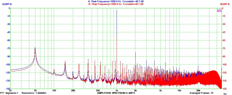
So there are people who say the 303 is the best Quad amplifier ever made. We don’t agree if you use the 303 with modern digital source material combined with high volume settings. This is one of the reasons we advise to monoblock a 303 or use it in a bi-amp application per channel. The load dependent cross talk can influence the stereo soundstage.

The next myth: high bias current

In the Quad service manual it is stated that the DC bias current of the power transistors must be between 10mA and 5mA. A popular “mod” is increasing the current to 35mA and in some cases even higher. Well, in real life the distortion is only 0.05% at a bias current of 0.5mA. At 5mA it is 0.01% and will not get lower at higher bias currents. Also the spectrum analyzer will not give a better (cleaner) picture at high levels of bias current. So Quad was (is) right! For practical reasons, stability of the circuit, 10mA is a good value for the bias current.

Joost Plugge

Virtins Technology
Sillanumsoft
ESI
Audio Precision

Labels: , , , ,

Wednesday, March 04, 2009

Hum

Most of the hum problems are related to “earth” loops in external cabling systems.
Input "hum" can arise from small ground potential differences between signal inputs and outputs.
The grounds between amplifiers are established by the AC outlets, and through signal cables. Various factors can cause small ground potential differences between the sound input (power amp) and output (pre-amplifier).
A one-volt difference, while seemingly insignificant, can cause large loop currents to flow through the ground conductor of the signal cable. Depending on the circuit configuration of the audio hardware, the audio signal impedance and the impedance of the signal cable ground, the currents may cause induced voltages in the audio circuitry.


Source: Channel D

This is a source of the familiar 'hum' problem.
In the “old” days, like the Quad 33 and 303 combination, the 303 has no separated ground connection. Grounding was done trough the signal cable between the 33 and 303.
The advantage of such a “star” system: no hum loops. With modern safety regulations such a star system is highly illegal in most countries, and more important, not safe.
In the multi channel (Stereo) world the problems are even more pregnant. Also in most cases the aerial connection of the tuner is also connected to “ground”. In professional installations signal transport is isolated from ground connections (balanced connections); in normal audio systems engineers mix signal ground and chassis ground.

How to avoid hum loops?

Use only one wall socket for the mains connection, if possible. Use the preamp and the associated cabling in the “star” configuration. Separate the safety ground and the signal ground in the power amp, so the chassis is connected to the safety ground of the wall socket, but not connected to the signal ground of the preamp. The same recipe for other equipment connected to the preamp (not always possible!).
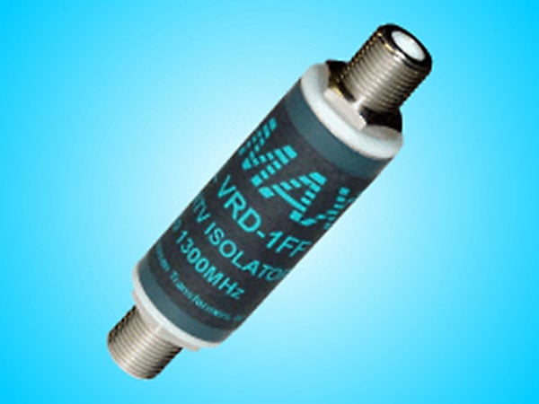
General advice; use cables as short as possible. Use shielded cables for the power cables. In some cases, a so called “isolator” is unavoidable; first test one in the aerial connection of the tuner. The tuner signal is FM modulated, so an isolator does less (no) harm to the signal quality. In RCA cables a small signal transformer play this role. Don’t spend a lot of money on special cables and end up with a cheap isolator in between.
In some cases increasing the resistance of the shielding of the signal cable has a positive effect, apply this only if the amplifiers have a proper installed safety earth connection!

How to detect and solve hum loops?

In general; a hum loop generates hum independent of the volume settings. If the hum is dependent on the volume setting; the hum is equipment borne in most cases. But the hum could also be a combination of both situations! The elimination of a hum loop is a painstaking process. Trial and error and applying logical thinking is the best solution.
Start with only the power amp and the loudspeakers, no signal cables connected. Then rebuild the configuration item for item. A cable is also an item! Once the source of the hum is known, a measure can be determined.

Measures

In a Quad 405 and 303 the chassis ground can be separated from the signal ground. In both amplifiers they are bonded together at the DIN input chassis part. In a 405 with factory fitted RCA inputs the two grounds are already separated. The same applies for a 606 and the higher numbers. In Quad tuners it is difficult to perform this trick, but in most cases the hum loop is caused by the aerial connection. A coaxial cable isolator will fix this problem. For testing and analysis it is acceptable to use a non earthed power extension cable for detecting the source of the hum, but always restore the safety earth connection to the chassis afterwards for your own safety! So you should *either* have 3-core mains leads from every piece of equipment *and* signal cables with the shielding disconnected at *one* end, if separation from the signal ground and chassis ground is not possible, or else a single mains connection and everything earthed via the signal leads, as in the case of a 33. Read also the comments before you change anything to your equipment!


A Jensen coax cable isolator


A simple DIY HF isolator!


Joost Plugge

Labels: , , , ,

Saturday, January 12, 2008

Quad 405-2 AC voltage considerations


From serial number 83000 and onwards Quad omitted the AC mains voltage selector on the Quad 405-2.
I recently checked such a late model Quad. It did not perform well. The power delivery was not on spec. On the outside of the unit there was a marking: 220V. But in real life the unit was wired for 240V. The Quad 405-1 had a selector with 6 positions, in the service documentation of the 405-2, only for four voltages is explained how to connect the wire links to the primary windings of the transformer. In the Netherlands the AC voltage is 230V, this is one of the missing voltages in the documentation, and the other is 130V. Because of the design, the DC power supply voltage of the amplifier is proportional to the AC mains voltage. So 130 V or 110 V does matter! To complete the documentation I drawn the missing link positions. You can also use these diagrams to rewire any Quad 405 and omit the voltage selector with those tiny wires. If you can hear a difference? I can’t tell you, judge for yourself. Before you rewire the amp, check the AC voltage during some weeks, check what is really coming out of the mains socket. Click on the diagram to get a fully detailed version, I also added some colour.

Joost Plugge

Labels: , , , ,

Saturday, June 16, 2007

"Quad 405" ?


Piet (NL) brought me a "405" he bought second-hand for revision.


I have seen a lot of things inside the > 250 Quads I had on my working-table but this beats everything.

The circuitsboards were replaced with Sanyo STK070 solid-state 70W amplifiers. It is clear that this way the 405 specs are far from being met.

Furthermore the internal wiring is a total mess.

One should always ask to see the inside when buying an amplifier second-hand.

We will build this 405 again, bottom-up, with 405 driver-boards.


It looks a lot better yet, doesn't it?

To be continued...

Stefaan

Labels: , , , ,