Step 4 - Upgrading the circuit-boards.The number of this circuit-board is M12565-6 (this is about the first 405-2 circuit-board). This means that the clamp-circuit is integrated on the board and that some improvements have been made about the current-limiting and the input circuit.

The first thing we'll do is connect it to a lab + & - 50 Volt power-supply to see what amount of power it eats. The - power-line should eat about 110 mA and the + power-line about 120 mA.

It passes the test well. This means the transistors are OK. (Zero Killed can be taken literally in this case). Both boards are OK.
The 0 Volt power-line has to be connected to the transistor-chassis. There is a 10R resistor between the input-circuit mass and the power-circuit mass. It will smoke if you are confused between masses.
OK, we'll remove all components that have to be replaced. We won't touch the other board for the time being. This way we can always compare.
We'll replace R3 with 1% metal-film low noise 22K.
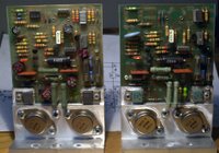

We'll replace D1 & D2 with 15V 1,3W.
We'll replace the electrolyts C4/C5/C18/C19 with new audio-grade caps.
We'll replace C2 and C10 with bipolar caps.
Of course we'll replace the opamp with BB604AP and the PCB connectors. The PCB-connectors have to be replaced because we have to redo the cabling. After more than 20 years they usually are oxydated anyway. We'll use 1,3mm silver-coated PCB-connectors here.
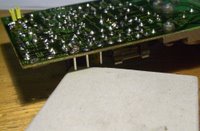
Soldering them to the PC Board is quite difficult as they tend to fall out and as they should be fixed very well in a horizontal way. I us a small carton box of 1 cm height to position them one by one.
We'll add 100 nF caps in the powerline of the chips on the backside of the PCB.
We'll also reduce the sensitivity of the input to 1,5V (from 0,5V). This will also reduce noise & distortion with another 10 dB.
We'll do this by increasing local feedback and DC feedback. We replace C4 with 150 nF MKT, R4 with 6K8 and R6 with 100K 1% metalfilm.

On this subject you should take a look at Bernd Ludwig's text and schematic (see the Quad-links in the left column).
Before adapting the second circuit-board we have to test the upgraded board to make sure it's OK. This way, if there is a problem, we can compare the voltages on both boards to locate the error.
Step 5 - Testing the circuit-boardsWhen both boards are upgraded we'll connect them to a sinus-generator and to the scope. We'll connect + and - 50 Volt with our lab power-supply and connect a true-RMS multimeter to check the input- and output voltages.

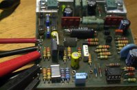
Following measurements are OK:
- 0,01 Volt DC on the outputs
- 30 .. 32 Volt AC on the outputs before clipping. This corresponds with 110 .. 125 Watt into 8 Ohm.
- 1,7 Volt AC on the input before clipping. This corresponds with line-voltage for full power.
If you don't have all this lab-equipment, skip this step. We will make sure later that there is O VDC on the output and that the power-consumption in the power-lines is 120 .. 130 mA. In this case we'll do Step 6 first.Step 6 - Cabling
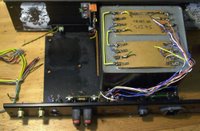
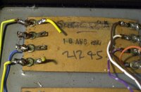
We start by cabling the power-supply. For internal cabling counts: the shorter the better. We'll use high-quality flexible 1,25 mm in 5 colors for everything except the 230 Volt lines.
We'll use following colors:

- Yellow for AC power-lines (between the transformer and the bridge)
- Red for the +50 Volt line
- Black for the -50 Volt line
- Green for the output-mass
- Blue for the LS-output lines
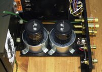
We do all the cabling of the Power Supply lines and test the voltages first. They should be around + and - 51 .. 54 Volt DC. Before connecting the power re-check the polarity of the caps and the rectifier-bridge.
Don't forget to connect the mass-lines of the capacitors (one + to one - side of each cap) and the ground-line of the transformer to the central mass-point on the chassis.
It is better to twist all cables that have to be soldered to the same point together before tinning them, it makes soldering them a lot easier. Foresee cables to the boards as well.
Warning If the polarity of the caps is wrong they will explode!
Once the power-supply is OK, we fix in both boards adding thermal paste to ensure maximum heat-conduction with the chassis.
We can now connect the + and - power-lines to the boards (don't switch them or you'll kill the output-transistors!) as well as the LS-output cables to the red LS output-plugs.


It is no luxury to use some Raychem (or other) Heat Shrinkable Tubing for insulating the +, - and output connections, as there are large voltages between them.
Before connecting mains-voltage we should check all cabling again with the Ohm-meter. We should alse re-check that each channel uses 120 .. 130 mA in the + and the - power-line and that there is less than 1 Volt DC on the outputs (typically 0,01 Volt).
If it passes these final tests we can now connect the speakers and the preamp and... enjoy the music ;-)
Stefaan




 The first step is to remove the top- bottom- and sidepanels. Sometimes, after 30 years, the screws are hard to remove. The best screwdriver to use is a Philips n°2 with a length of at least 20 cm.
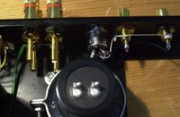
 -plug with normal wire.


 Following measurements are OK:

