
Hum
Most of the hum problems are related to “earth” loops in external cabling systems.
Input "hum" can arise from small ground potential differences between signal inputs and outputs.
The grounds between amplifiers are established by the AC outlets, and through signal cables. Various factors can cause small ground potential differences between the sound input (power amp) and output (pre-amplifier).
A one-volt difference, while seemingly insignificant, can cause large loop currents to flow through the ground conductor of the signal cable. Depending on the circuit configuration of the audio hardware, the audio signal impedance and the impedance of the signal cable ground, the currents may cause induced voltages in the audio circuitry.
 Source: Channel D
This is a source of the familiar 'hum' problem.
In the “old” days, like the Quad 33 and 303 combination, the 303 has no separated ground connection. Grounding was done trough the signal cable between the 33 and 303.
The advantage of such a “star” system: no hum loops. With modern safety regulations such a star system is highly illegal in most countries, and more important, not safe.
In the multi channel (Stereo) world the problems are even more pregnant. Also in most cases the aerial connection of the tuner is also connected to “ground”. In professional installations signal transport is isolated from ground connections (balanced connections); in normal audio systems engineers mix signal ground and chassis ground.
How to avoid hum loops?
Use only one wall socket for the mains connection, if possible. Use the preamp and the associated cabling in the “star” configuration. Separate the safety ground and the signal ground in the power amp, so the chassis is connected to the safety ground of the wall socket, but not connected to the signal ground of the preamp. The same recipe for other equipment connected to the preamp (not always possible!).
General advice; use cables as short as possible. Use shielded cables for the power cables. In some cases, a so called “isolator” is unavoidable; first test one in the aerial connection of the tuner. The tuner signal is FM modulated, so an isolator does less (no) harm to the signal quality. In RCA cables a small signal transformer play this role. Don’t spend a lot of money on special cables and end up with a cheap isolator in between.
In some cases increasing the resistance of the shielding of the signal cable has a positive effect, apply this only if the amplifiers have a proper installed safety earth connection!
How to detect and solve hum loops?
In general; a hum loop generates hum independent of the volume settings. If the hum is dependent on the volume setting; the hum is equipment borne in most cases. But the hum could also be a combination of both situations! The elimination of a hum loop is a painstaking process. Trial and error and applying logical thinking is the best solution.
Start with only the power amp and the loudspeakers, no signal cables connected. Then rebuild the configuration item for item. A cable is also an item! Once the source of the hum is known, a measure can be determined.
Measures
In a Quad 405 and 303 the chassis ground can be separated from the signal ground. In both amplifiers they are bonded together at the DIN input chassis part. In a 405 with factory fitted RCA inputs the two grounds are already separated. The same applies for a 606 and the higher numbers. In Quad tuners it is difficult to perform this trick, but in most cases the hum loop is caused by the aerial connection. A coaxial cable isolator will fix this problem. For testing and analysis it is acceptable to use a non earthed power extension cable for detecting the source of the hum, but always restore the safety earth connection to the chassis afterwards for your own safety! So you should *either* have 3-core mains leads from every piece of equipment *and* signal cables with the shielding disconnected at *one* end, if separation from the signal ground and chassis ground is not possible, or else a single mains connection and everything earthed via the signal leads, as in the case of a 33. Read also the comments before you change anything to your equipment!
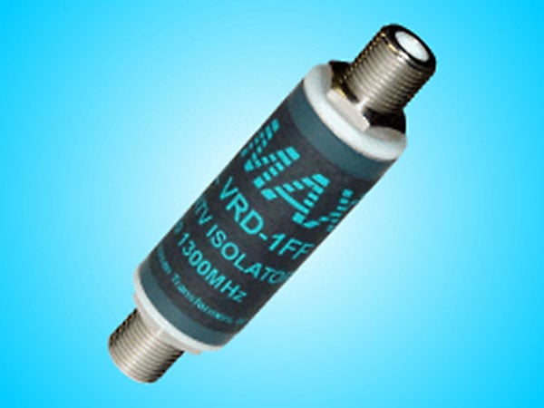
A Jensen coax cable isolator

A simple DIY HF isolator!
Joost Plugge
Labels: 405, amplifiers, Quad, Quad 306 Vintage Amplifier, vintage
posted by Stefaan @ 6:40 PM
11 comments


