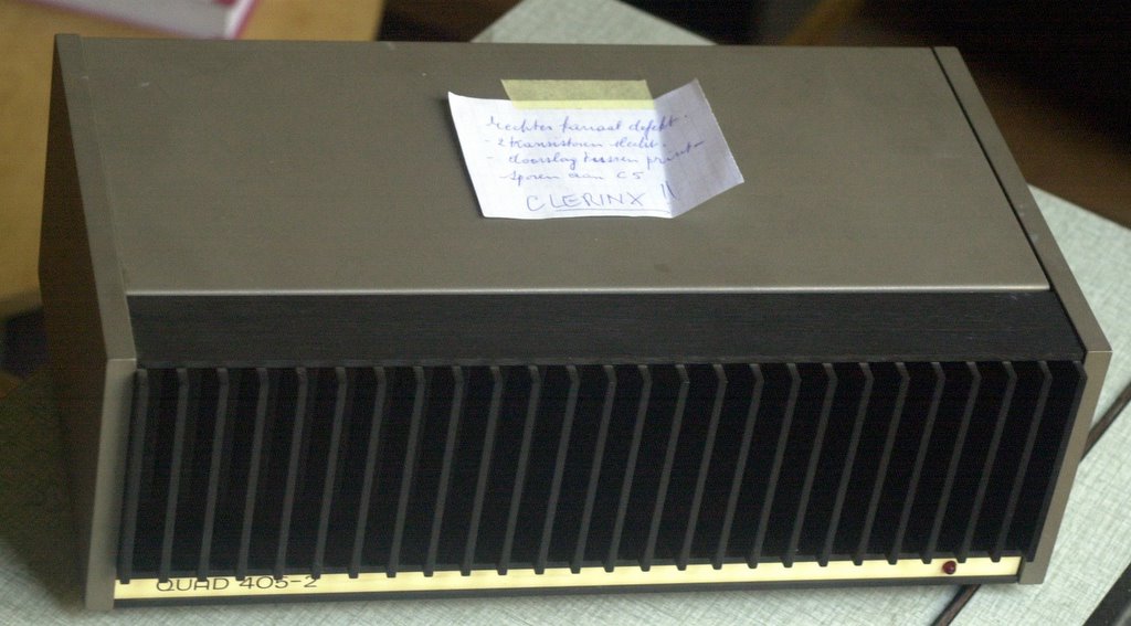
Quadrevision Live: The Quad/Rogers 405 studio monitor
A very interesting amplifier has fallen into my hands!
Quad used to make OEM amps for the BBC, as studio monitors.
Quad worked together with Rogers, which made an active 2-channel filter with symmetric .650 V inputs and the loudspeakers that go with it.
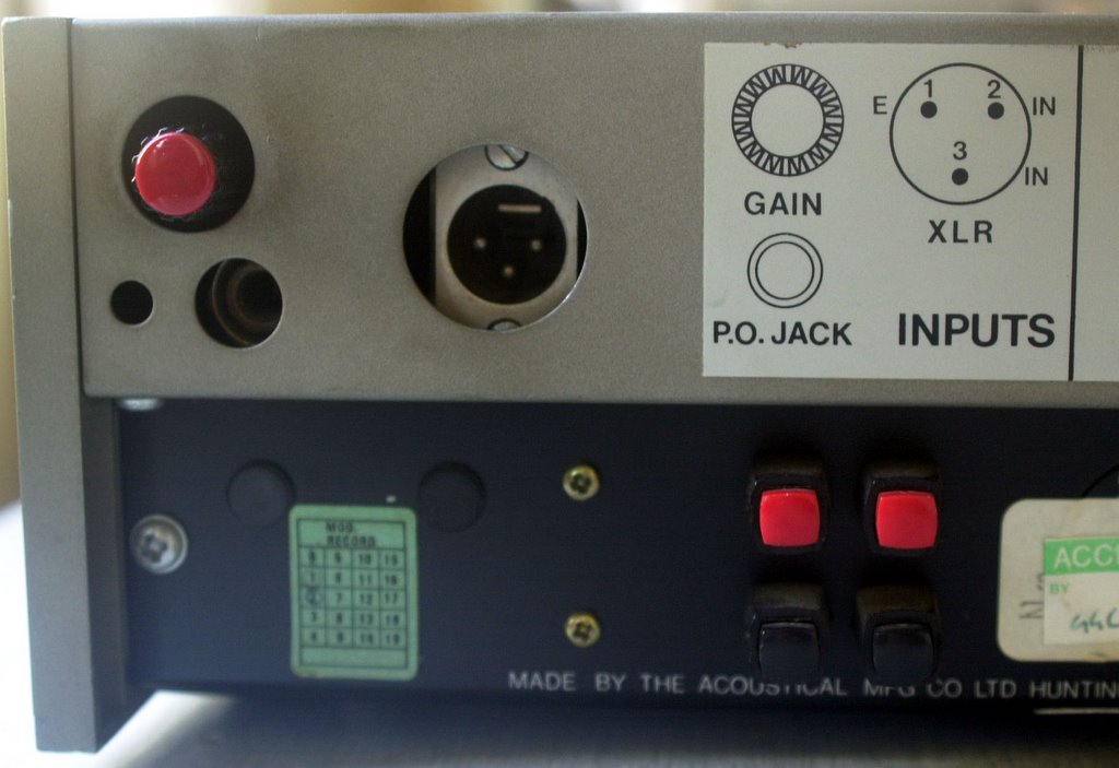
The left channel of the 405 is used for the high tones, the right channel for the bass-tones .
The tweeter-channel is limited with the voltage-limiter originally intended by Quad for connecting the ESL speakers. Nice ;-)
Specific Neutrik-cables were designed for the set to connect the speakers and to connect the inputs to a symmetric pre-amp or mixing-table.
Revision step 1: Making a phase-shifter
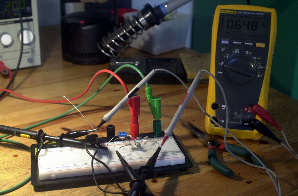
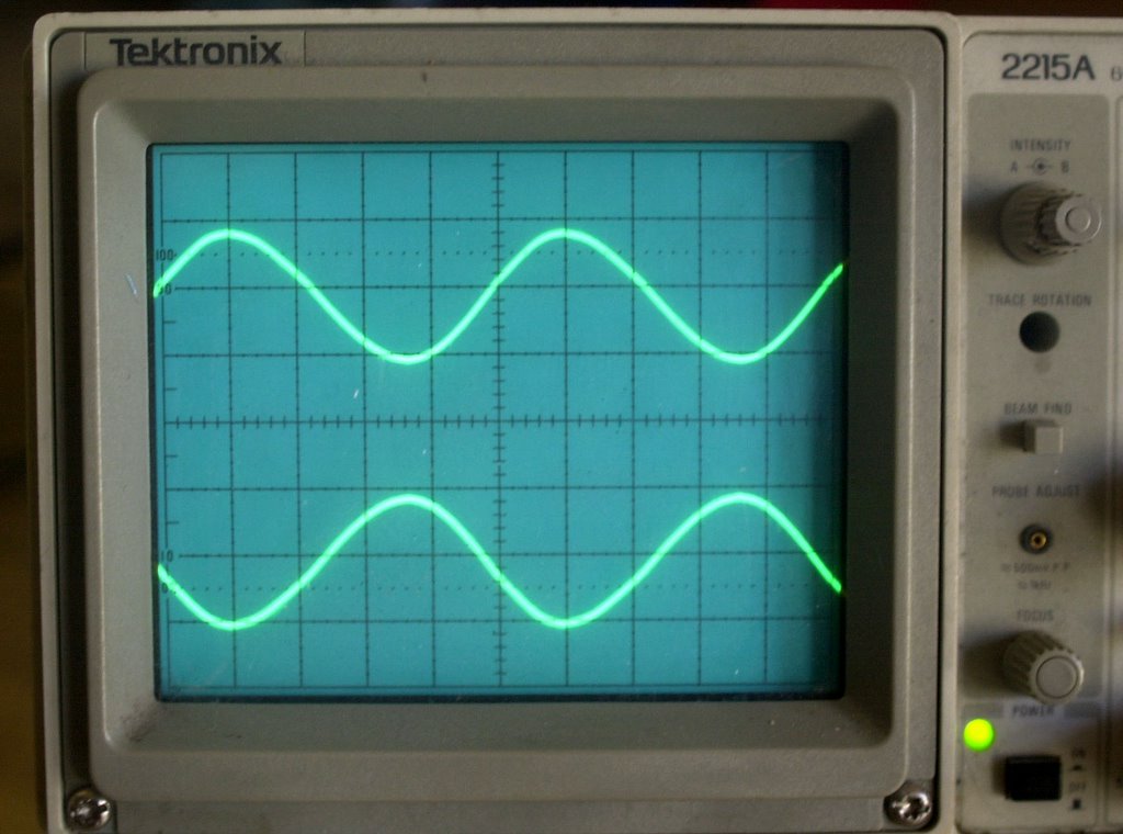 As the input is a symmetric one we'll have to make a phase-shifter in order to connect the signal-generator in a symmetric way to the filter for measuring-reasons. With a breadboard and a single transistor this can be done in 5 minutes.
Now we are ready to measure the filter and check the bandwidth of both low and high channels on the scope. We will use a 1 KhZ .650 Volt sinus to start with.
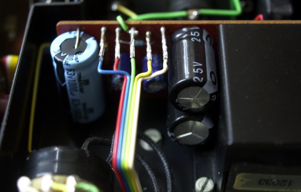
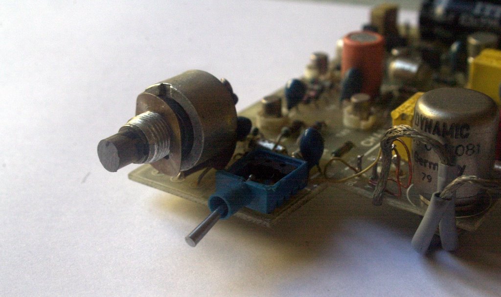
But first we'll have to replace the old capacitors on the filter-board. Rogers used Tantalum capacitors that are awful for audio-applications but I guess they were fashionable in the 7-ties %-)
I'll take my bike and go to the electronics-shop. See you later.
In the meantime you should also take a look @ http://www.mhennessy1.f9.co.uk/rogers/ls58.htm
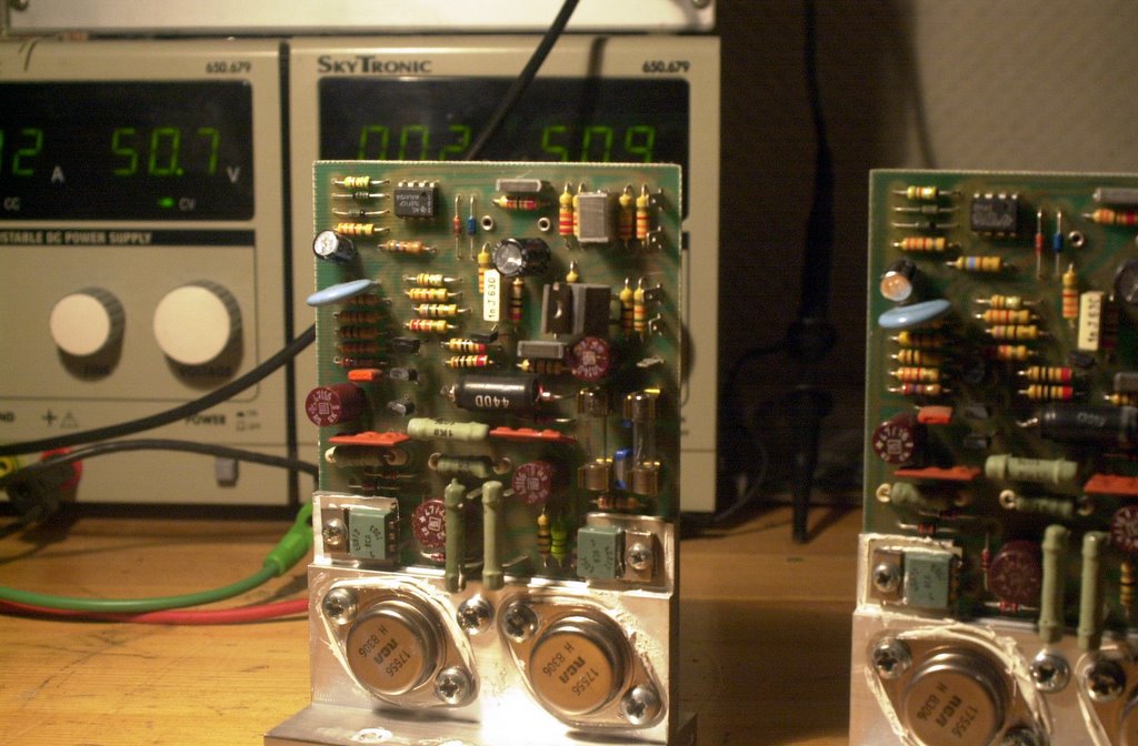
Revision Step 2: Checking the Filters
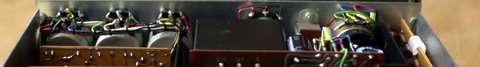
 Revising and upgrading the 405-modules was straightforward, as I did about 100 of them before. Both amps (you have one per Rogers 5/8 speaker of course) have been made with +/- 4 years difference (1979 and 1982).
I think this is normal, the BBC ordered several hunderds of them from Quad/Rogers for on-the-road usage and stored them in the same warehouse. We can not expect similar pairs to stay together.
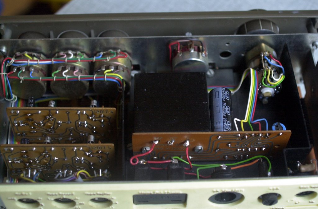
We are looking @ 2 405's with totally different Rogers-filters inside. Since 1982 Rogers removed the "Bass boost" option and simplified the schematic. The newer filter shows a strong distortion due to the input-transformer, which was to transform the symmetrical input to a non-symmetrical signal for the filter.
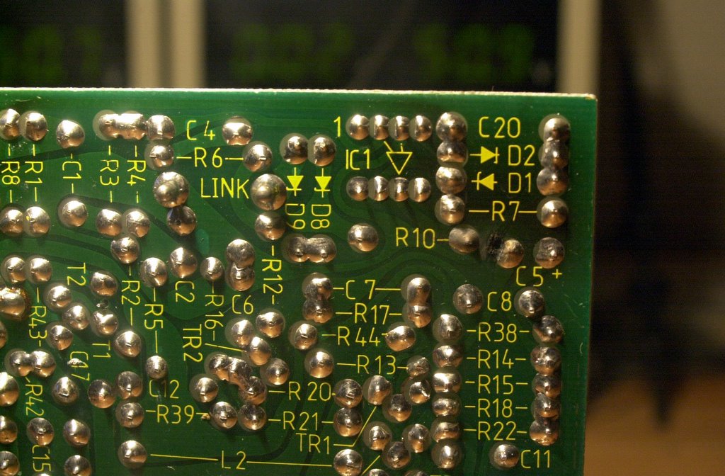
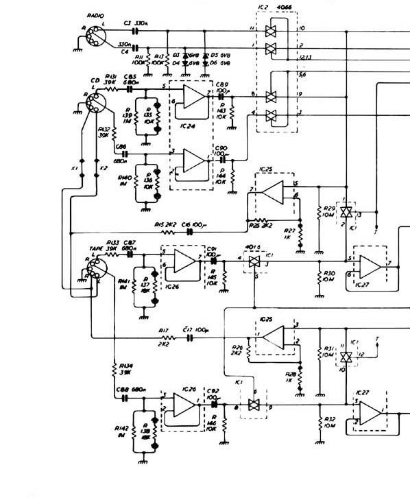
The Rogers-filters were built with transistors and very old components and there are no schematics to be found...
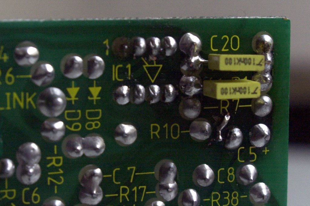
Revision Step 3: giving up the project...
There were many reasons why Jean-Marie and myself were very unhappy with the Rogers crossover filters.
Rogers used a small transformer to change the balanced input-signal to unbalanced in the input-line. Although this transformer does the job it causes a lot of distortion and phase-shifting.
The filter is made with transistors and some very old components, some of which were broke. The schematics can't be found.

So we decided to remove the filters, upgrade the Quad's and use a Behringer active filter instead.
Jean-Marie bought one for only 100 Euro. New, with a 2 year warranty. We'll connect it next week and we'll keep you posted...
What Peter Walker said about active crossovers (In an interview with Adio Amateur, 1978):
"AA: Some people like splitting up the signal with electronic crossovers, Do you see problems in that?
You can read the full article on The Audio Circuit (http://www.audiocircuit.com).
Stefaan
posted by Stefaan @ 1:27 AM
1 comments
![]()
![]()