Wednesday, September 06, 2017

Misprint in Quad 99pre manual.

Misprint in Quad 99pre manual.

Several 99pre owners have complained of low volume and dull sound from the phono preamp. We traced this to an error in the user manual on page 10. It shows an example:

    moving-magnet input selected             PH 00

which should read

    moving-magnet input selected             PL 1.00 (or 3.00 or 7.75)

or else

    moving-coil input selected     PH 00

This is a mixup between 'high sensitivity' (MC) and 'low sensitivity'
(MM). Most people, us included, and perhaps the manual writer as well, think from the cartridge end, 'high output' (MM) and 'low output' (MC).
So 'high' and 'low' mean opposite things depending on whether you're talking about sensitivity or output level. The instructions given later on page 15 are correct.

So what these owners had done is set up their phono inputs as moving-coil, which has a very low input impedance, so most of the signal is lost, and the inductance of the cartridge plays an undue part in the LR filter formed by the cartridge and the input impedance. Setting it up for moving-magnet PL 3.00 solved the problem in every case.

Esmond Pitt

Dada Electronics Australia

Tuesday, September 05, 2017

An exploration of the practical issues and benefits of two of the Quad 405-1 modifications suggested in Berndt Luwdig's paper on the Quad 405.

These modifications are not for the inexperienced or those without adequate test equipment, and are not under consideration for inclusion in any Dada Electronics Kit. The D13 modification is included in our HE 405 board. This article is provided for information only. Use at own risk.

This article is an exploration of the practical issues and benefits of two of the Quad 405-1 modifications suggested in Berndt Luwdig's paper on the Quad 405.

The first of these is the addition of D13, as found in the 405-2 and later Quad current dumping amplifiers: 606, 306, 707, 909. The Quad service manual refers to this as 'correcting the response at 20KHz'. For brevity I will call this the 'D13 modification'.

The second is an alteration to the current limiting circuit to bring it more into line with what the networks N1, N2 do in a 405-2 or later current dumping amplifier. It consists of the addition of two 36V zeners and some resistor value changes around Tr5 and Tr6. It raises the current limits closer to the 405-2's, which enhances high-power performance into 4-ohm (and
2-ohm?) loads. For brevity I will call this the '36VZ modification'.

1. D13 modification. This is very straightforward to implement, just requiring removal of D5, cutting the track to the base of Tr9, and replacing
D5 with a 1N4003 diode from its anode connection point directly to Tr9 base and adding another 1N4003 from there to the original cathode connection point for D5, both now located on the track side of the PCB, both oriented 'cathode down' in the circuit. D6 should also be replaced with 1N4003. All this is better described in the Ludwig
paper: interested readers should certainly refer to that, rather than taking this bald description as an adequate specification.

However I had considerable difficulty with this modification. After much time and trouble this was eventually tracked down to two problems:

1.1 A faulty triac in the clamp circuit. Somehow this was behaving like a shunt capacitor presenting very low impedance at 20KHz, so when I tested with a large enough signal I would blow both power transistors and rail fuses. I was testing into an instrument with 100k input impedance at this point, not an 8 ohm dummy speaker load, so the current limiting didn't save me. I eventually found this fault by powering off the 405 and injecting the test signal into the speaker terminals, and measuring it, which showed the low impedance and low-pass filter/shunt capacitance behaviour.

1.2 A major slew-rate problem from about 4KHz upwards. This was eventually tracked down to Tr5 and Tr6. The 36VZ current-limit modification had already been applied, so it is uncertain whether that modification brought out the behaviour in these two transistors, which were the original BC214s, or whether they were already faulty. In any case they seem to have had some kind of excess capacitance issue, which was resolved by replacing them both with BC560. (The 36VZ modification is therefore not to blame.) So I would recommend replacing both these transistors before attempting the D13 modification.

It would be difficult or maybe impossible to even spot this problem without a signal generator and oscilloscope and/or distortion analyzer, and unless it is absent or resolved there is no point whatsoever in the
D13 modification, as the slewing distortion will completely mask it.

When complete, the D13 modification improved the THD of the amplifer as
follows:

1KHz: 0.0225% became 0.0062%
10KHz: 0.0217% became 0.0095%
20KHz: 0.028% became 0.0095%

IMD (DIN method, 250HZ and 8KHz in 4::1 ratio, 4VRMS output level):
0.0125% became 0.0077%

SNR: Unchanged.

Measured with Tektronix SG505 and SG505/01 oscillators and AA501/01 distortion analyzer at 4VRMS output level into an 8 ohm dummy load, i.e.
2 watts. (I rarely test at full power.)

It should also be noted that with the D13 modification, the upper dumper
Tr9 now comes on a bit sooner than Tr10, as you can intuit by measuring the standing b/e voltages on both; and the signal at the base of Tr10 is no longer symmetrical. The former doesn't matter much, as it only imposes a tiny extra load on Tr9 at very low signal voltages around
0.5VRMS: the latter doesn't matter at all: you are going to see all kinds of strange signals inside any feedback amplifier anyway.

2. 36VZ modification. This is very straightforward, as described in Ludwig.
I adopted the solution of scaling up all the resistors as described there, rather than using 2W resistors. I had no trouble with this modification beyond getting the diodes the right way around. The lower zener/resistor combination is fitted near the fuses and should be insulated from contact with them.

Esmond Pitt
Dada Electronics Australia
Copyright (c) Esmond Pitt, 2017. All rights reserved.

Sunday, April 26, 2015

Bias Stability in a Quad 303

I had set the bias in my own Quad 303 in 2006 or 2007 with the aid of a high-quality Tektronics AA501 distortion analyzer and oscilloscope. This technique clearly shows cross-over distortion spikes when present, so it is easy to arrive at the minimum bias setting required to eliminate cross-over distortion. By this means I usually arrive at somewhere around 10-12mV across the emitter resistors.

Out of curiousity I checked this 303 over the weekend using the same distortion analyser. This check showed that after 8-9 years of daily use for several hours a day (about 7200 hours in total) there was absolutely no need for any re-biassing. This shows that the Quad 303 'triples' design really does work.

This 303 has a set of very early Dada Electronics 303 boards in it, which also goes to show that they have been entirely trouble-free over that quite long period.

Esmond Pitt, Dada Electronics Australia


1. The scope picture shows the signal in the upper trace and the distortion residual in the lower trace. Some tiny cross-over spikes just emerging from it, corresponding to the zero crossings of the signal.
Note that there is no 2HD or 3HD visible at all: they would show up as waves at double or triple the signal frequency.

2. The THD+N is .0096%.

3. The signal-to-noise ratio is -83.9dB.

All measurements taken at 1kHz, about 6V RMS across 9 ohms, or about 4 watts. For lab reasons I don't go much higher than this, but I also don't consider it relevant, as this is about the maximum level I listen to. It should be noted that at full power the THD+N would increase a little, but the S/N ratio would improve.

Equipment used: Tektronix SG505 oscillator, AA501/01 distortion analyzer, SC504 oscilloscope.

Saturday, February 28, 2015

Counterfeit Warning 405 boards

Recently counterfeit Dada Electronics High-end boards have appeared on Tweedehands.be and Marktplaats.nl. Also on eBay.


Those boards are counterfeit based on the schematics for the boards developed by JP Engineering for Dada Electronics. The schematics and PCB designs were stolen by an individual who worked for us, he was mounting those boards.
We had to stop the cooperation because of sloppy work and because this person appeared to have no VAT-number and worked illegally without being inscribed in the register of commerce.

JP Engineering and Dada Electronics will take legal steps against this fraud.

In the meantime we recommend our customers  to make sure you do not buy those boards as Dada Electronics will not give any technical support for them and there is no legal warrantee as they are not produced by an officially existing company.

You can recognise the counterfeit boards by lacking (c) JP Engineering (JPE) or (c) Dada Engineering mark.
The same counts for the offered 606 power supply boards.

Stefaan Verdonckt & Joost Plugge.

Sunday, October 19, 2014

Input Sensitivity of 'Power' amplifiers, the 306/606 case


The recent discussion on the forum about the input sensitivity of a Quad 306 and 606 in a Bi Amping application is the reason for this post.

First let me get things straight:

A ‘power’ amplifier is a voltage amplifier! The delivered power is the result of the applied voltage to a load, most of the time a loudspeaker.

A loudspeaker is not a power transducer, but a voltage transducer! The absorbed power is a result of the voltage output of the amplifier applied to the impedance of the loudspeaker.

Why is everybody (including me) talking about power? Well, this is successful brainwashing marketing, like the Horsepower for cars. The HP is only a meaningful value if you now the revs and the torque, so is power in amplifiers and speakers only a meaningful value if you now the impedance and the frequency concerned.

Input sensitivity of amplifiers is defined as follows (regrettable): the voltage at the input that is needed for delivering maximum power in a 8 Ohm resistance at 1kHz and  with a total harmonic distortion of 0.1%.

Sometimes amplifier manufacturers use different standards, but the impedance, distortion and frequency should be specified.

This ‘Power’ way of thinking leads sometimes to wrong conclusions and assumptions. An example; in some HiFi magazines the output power is measured in other impedances than 8 ohm. In some cases the output power is halved, which seams low fi. But the output voltage is only 3dB lower, so within limits that are excepted by the HiFi community.

The 306/606 case:

The 306 has a sensitivity of 375mV for delivering 50W in 8 Ohm.

Power is the squared voltage divided by the impedance. P=U x U / R

So in the 306 case the output voltage is 20V

The 606 has a sensitivity of 500mV for 140W in 8 Ohm

The output voltage is 33,47V

In a Bi Amping setup the voltage delivered to the tweeter and woofer section should be the same given a value of the input voltage, otherwise the loudness will not be even spread amongst the total spectrum.

So we are interested in the voltage gain of the amplifier, this the ratio of the output voltage and the input voltage (U out / U in).

For the 306 this is 53,33, for a 606 this is 66,94 this looks far apart, but in decibel terms this is 1.97 dB, within the limit of 3dB. (dB is 20 x log Gain 606 / Gain 306). In practice the bass is a little bit louder, if the 606 is used to drive the woofer section. Which is logical, because of the rule of thumb of Stefaan; 90% of the power is delivered below 1000Hz.

If you want the voltage gains exactly right, the sensitivity of the 606 should be lowered, how much? The voltage gain of the 606 should be 53,33, so the input voltage should be 33,47 divided by 53,33 is 628 mV. This can be done by replacing R11 from 7.5 Ohm to 9.4 Ohm. This is not a practical value, so we choose 10 Ohm.

The voltage gain of the 606 is (33.47 / 0.5) x (7.5 / 10) is 50,21.

The difference in db is now: 20 log 53,33 / 50,21 is 0.52 dB. Which is as close as we can get with standard components (or use 18 Ohm and 20 Ohm in parallel as a replacement for R11).

Joost Plugge


Friday, October 11, 2013

Mono blocking or Bi-Amping


Monoblocking or Bi-Amping?

There are three ways to let the two channels of a stereo amplifier work together to drive a single loudspeaker.

First there is the serial monoblock. The speaker is connected between the two ‘hot’ outputs and the inputs are driven in anti-phase. The output part is simple, but for the input you will need a separate circuit or a special input transformer. The disadvantage of this way of monoblocking is as follows; it will deliver more power, but in higher impedances. So for modern low ohmic speakers this is not a good solution.

The second way is the so called parallel monoblock. On the output side you need resistors to function as a current sharing circuit. On the input you need a potmeter to make the output voltages of the two channels equal before the current sharing resistors. Now the combined amplifier deliver more current, this is a big advantage for modern speakers. The amplifier clipping point is at higher volumes and the distortion will be lower at the same volume level.

The third technique can only be  applied if your loudspeaker has a separate input for the treble and woofer section, it is called Bi-Amping. It is very simple, remove the wire or strip of the speaker terminals and connect the two amplifier channels with separate cables to the speaker inputs. On the input you need a special cable or coupler to split the signal coming from one channel the pre amplifier and connect it to both the inputs of the power amplifiers. In this way you have applied so called vertical Bi-Amping. There is also a variant called horizontal Bi-Amping and is necessary if the two stereo amplifiers are of different power rating. The vertical Bi-Amping shares the advantages of the parallel monoblock because the single amplifier channels will ‘see’ a higher impedance.

The big advantage of Bi-Amping; no work have to be done inside the amplifiers!
Comment on the picture, a Bi-Amping setup with a high WAF factor!


Joost Plugge

DaDa Electronics

Saturday, April 27, 2013

PGA2311 based (remote) volume control


There was a question on the forum about a remote controlled volume control, the intention was to place it between a Quad 33 and 303. At that stage we could not help, so we advised to look at a kit or a complete unit based on a PGA2311 chip. On eBay there are plenty of companies who can deliver such a box or kit in various forms. I also bought such a system as a kit, more or less a kit, the electronic modules are already assembled. After a few weeks the kit was delivered. I had to ad a transformer and some mechanical fixings to get the kit operational. Some first remarks, there was no manual provided, so this kit is not for absolute beginners. Secondly there was no provisioning for a fuse holder. I measured the unit, it performed well. It sounded just allright. I found a schematic on the web. I checked the schematic with the unit under test, the schematic matched my unit. I also downloaded the datasheet of the PGA2311. The first problem was there already, the unit was DC in and DC out on the signal in and outputs, for my own equipment I find AC in and DC out acceptable, but for a commercial and/or professional product, AC in and AC out is the norm. Also they added 10K resistors in parallel to the input, probably they thought the input was connected via a buffer stage, but the input of the PGA2311 behaves like a 10K resistor already. In this way they effectively reduced the input impedance to a lowish 5K. This (can) give serious frequency response errors when driving from an AC coupled high impedance source preamp. According to the datasheet the PGA2311 input must be driven from a low impedance source, our friends put 220 Ohm in series with the input, with higher distortion as a result. The 220 Ohm resistors make sense, if you complement them with small caps to form a RF/EMC filter, but without those, you only add distortion. Also they 'forgot' the decoupling capacitors which must be placed as close as possible to all the power supply pins of the PGA2311. In the output they put 330 Ohm resistors, in it self a good thing for stability when driving real cables and inputs of power amps, but 150 Ohm is a better value or compromise if you wish.

So I replaced the 10K input resistors with 220K bleeder resistors. The 220 Ohm series resistors in the input circuit where replaced by 220uF bipolar capacitors, this might look as overkill, but to keep the distortion of the capacitors low, you have to reduce the AC voltage across the cap. And I put all the decoupling capacitors in place, according to the datasheet. The resistors in the output where replaced by 150 Ohm. The unit measured and performed ok, this unit was programmed for 1dB steps, which worked very good. Also you could select three sources. Which makes it a preamp. The only thing which wasn't there was a balance control.

A general remark about the PGA2311 chip, it will only give very low distortion when it is used with high level signals, high levels compared with the Quad standard of 500mV for their power amp inputs and pre amp outputs.

So to get minimum distortion, the levels between the Quad equipment must be raised. So the output of the preamp must increase, but more importantly the input sensitivity of the power amp must be set lower. The PGA2311 based unit performs at his best when the 0dB setting means full living room volume.

Then the last check. I bought a PGA2311 PA chip from our regular supplier and placed it in the unit...........The distortion and noise went slightly up! So the chip supplied was a real PGA2311 PA. Very good indeed!


Good things:

  • Very good casing and mechanical work.
  • Electronic modules were perfectly built.
  • Price quality ratio.
  • Remote controled.

Improvements:

  • Ad some form of manual, real or downloadable.
  • Follow the advice in the datasheet from the manufacturer about decoupling.
  • Redesign the input and output circuit to make it a real world preamp.

So with some work, you can improve this kit or unit from good to very good!

 Ps, the display is blue, I changed it with a red filter!

Joost Plugge

DaDa Electronics

Wednesday, April 10, 2013

Dada Electronics has chosen Nigel Grey photograpy as their home-photographer.

 
The Dada v2 Quad 405 High-end board. (c)

Friday, March 15, 2013


 Dada proudly announces the new 405 v2 High End boards


We used a double sided board with fully metalized holes. We had to do this to fix all the layout issues in the original Quad design. Also we where able to increase the distance between the input and output circuit. The collector current of the pre drivers was through a nut and bolt in the original design. This is a pretty awkward way to conduct current! So in the new design we use the centre pin of the transistor to do this. Also the TO-3 output transistors have their collector current now guided trough two nuts and bolts instead of the single one in the original design. All the tracks are widened and shortened where possible. It is possible now to split the power supply tracks to prevent the dumpers to pollute the tracks of the class A stage. So from a mechanical point of  view; this is the best 405 PCB ever produced. 

We also made some changes to the circuit itself. The Op Amp circuit is now a non inverting configuration. This reduces the noise to the excellent 606 level. We use a transistor to stabilize the power supply voltage of the op amp, this strongly reduces the switch off noise. The current source to drive Tr2 is also improved using a transistor instead of the capacitor in the original design. We also introduced extra power supply rail decoupling by means of electrolyte capacitors. All the electrolytes are decoupled with small film capacitors. For the critical capacitors we use polystyrene audio grade capacitors. The current limiters are optional. But the layout faults in the current limiting circuit concerning the position of the class A stage are solved. So the Class A stage Psu rails are not modulated by the dumper currents anymore. The current dumping bridge is rearranged and has the same layout as in the excellent 606 designs.

The new v2 High-end boards are now officially launched and available in the Webshop.

http://www.dadaelectronics.eu/shop/dada-high-end-boards

Saturday, January 12, 2013


Important news about connecting a DaDa double PSU in a Quad 405

I had some mail conversation with Keith Snook of DC- Daylight about double PSU’s, with or without the active ground and the protection options. Keith mentioned extra noise and 100Hz peaks when using double PSU’s. I did not have a clue, but lucky for us all, Keith solved the mystery, but also had a cure for it.

The 405 transformer is built up as a so called C core. Apparently they built it with two identical sections around the C core. If you look at the connections, you will recognize the symmetry.  So it looks like a secondary is closely coupled to its partnering primary, but more or less loosely coupled to the second primary section. In the original setup, see the 240V AC example in the drawing, all the secondary’s are connected in series and then in parallel, so each section only drawn halve the current from the primary side, and the load is balanced across all the primary’s and the secondary’s.

When you split the two secondary segments in the normal way to build up the dual supply, the load balancing is gone. This unbalance and the ineffective coupling of the first secondary and the second primary give rise to nonlinear behavior with the effects mentioned by Keith as a result.
The cure is simple, Keith find a way to balance the load across the primaries and the secondaries. See the drawing in the 230V AC example. To make maximum use of this balance, also the primary side must be connected in balance with all the AC mains voltage options. So when you have to rewire for a different voltage setting instead of clicking the voltage selector switch setting with the older 405's, look at the diagram for the correct layout.

Joost Plugge
DaDa Electronics

Wednesday, July 20, 2011

Chinese Quad 405 boards


On Ebay Chinese boards for the Quad 405 are for sale.


We ordered some to try them out.


They are based on the first version of the 405 board with some modifications in the in- and output connectors.


They will not fit the original aluminium heatsink-profile and they are 10mm longer and 5mm larger than the original board so they won't fit in a 405 but they may be interesting for DIY-projects in another chassis.


They come without schematic diagram or documentation.


Stefaan

Friday, May 06, 2011

Fixing Quad 303 boards in the chassis


We often get the question if we can supply the plastic clips for mounting the Quad 303 driver-boards and power-supply boards in the chassis, as they can break off while removing one of the boards.


In fact a simple and cheap alternative solution is using 4 mm plastic cable-ties, like in the pictures.


They are sold in most hardware-stores or in the Velleman cable-ties set we sell in our Webshop.


The 303 in the pictures belongs to Ad from the Netherlands and has been fitted with Dada High-end boards, new MJ15003 and MJ802 transistors and better internal cabling.


(Click on the pictures to enlarge.)


Stefaan

Thursday, May 05, 2011

BHC Aerovox ALC10C instead of ALP22A in Quad 606-Mk2, 707 and 909


BHC recommends using the ALC10C capacitors instead of the older ALP22A in new developments. It is less expensive, smaller and it has better specifications. The ALP22A is still produced for replacements in older circuits (but is out of stock for the moment, new stock is announced for July 2011).


In the Quad 606-Mk2, 707 and 909 the ALC10C 15000µF 63V can be used but the pins won't fit the printed circuit board. This can be solved by cutting the two unconnected pins and drilling an extra hole 1,5mm) in the PC-board (see the picture).


Make sure to double-check the polarity, when the polarity is wrong the capacitors will be damaged. The - pin is beside the gold line on the side and it has a "-" sign on it. The + pin is the middle one of the 3 pins on the other side. The two pins beside it have to be cut.


Dada is developing an new Printed-circuit board with a 500 Watt Amplimo transformer and 4x BHC ALC10C 15000µF for replacing the transformer and the capacitors in a 606 Mk1, making it an Mk2.


The 15000µF 63V ALC10C can be bought in the Webshop here.


The (general) BHC Aerovox datasheet can be downloaded from our Website.


Stefaan

Monday, March 14, 2011

405-clone needs service after 30 years...

Holger (from Germany but now living in Australia) has been using his 405-clone for 30 years but then there was this 18th Birthday-party of his daughter...

Back in the old student days 30 years ago some friends were obsessed with the idea of building audio equipment and one project amongst many others was to build a replica of the Quad 405.

The benchmark was to get better measuring results than the ones published by Quad and following some hard work and applying what was taught at Uni, the result was impressive.

Thanks to choosing better components, using custom built inductors, redesign of the power supply etc. we achieved what was then shared around a circle of mind-liked people.

The unit never failed in 30 years time, but has recently given up following a wild 18's party of my daughter.

Thanks to the team of DaDa Electronics it will hopefully spring back to life and will last another 30 years...

Holger

Saturday, February 05, 2011

Ivor's Quad 33 revision

Quad 33 Revision. A beginners tale.

I am a professional violinist who also has a small recording studio, and In the past couple of years I have built a small collection of Quad amps. This currently includes a 33/303, 405-2 and grey 44/606mk2. I realised after years of trying different equipment, both for domestic listening and in my studio that the Quad power amps are perfect for my needs. They are fairly cheap, built fantastically well, and sound great. I use the 303 with Quad Esl 57's , 405-2 with Harbeth P3ESR (In the studio) and the 44/606 await Harbeth Super Hl5's. The big problem I have experienced is with the Pre-amps. The 33 just sounded dull to my ears, and I could not enjoy using it even after a Quad service. I still have a large record collection so need a phono stage, and I like the look of the Quad preamps, but needed to try to improve the sound to the point where I felt I could use them whilst keeping as much originality as possible.

Dada kits seemed like a sensible proposition without costing too much. The down side for me was I have had absolutely no previous electronics experience except for a couple of poor attempts at soldering broken mic leads. Here are some perceptions I experienced whilst doing the work.
I had to do some basic web searches to work out the values of resistors, and youtube provided me with tuition on soldering and the use of solder pumps. Initially I just wanted to do the power supply modifications, and although there was a picture provided of the modified board, I did manage to put a couple of capacitors in the wrong way round. (Negative to positive) . I experienced some issues then when trying the preamp as my mistake had damaged the two new capacitors. A couple of emails to Stefaan in Dada support sorted that confusion out, and when I refitted the new Capacitors (which I re-ordered from Dada) the preamp worked like a dream and that “dull” sound was replaced with much more transparency.

Success lead me to want to do all the 33 modifications in the kit (except the reduction in input sensitivity since I use an Fm3 Tuner). The biggest problem I then experienced was coming across slight variations in board layout of the Disc Pre Amplifier Board M12019 (issue 4) and Tape Adapter Board M12027. Since I cannot read a circuit diagram yet or don't actually really know what the components even do yet, I was stuck.

The instructions from Dada are very good, but a few colour photographs of finished boards would have helped me. I found a site online where someone had completed the Dada mods on his 33/303, and using his pictures of finished boards that had the same layout as mine, I was able to work out the placement of a couple of components. I then took photos of my completed boards and sent them to Stefaan at Dada to make sure I had not made any silly mistakes. (I enclose my pictures of those two boards after modification)

The end result is that I now have an extremely good sounding preamp that cost relatively little, and looks perfectly in keeping with the rest of my equipment. It took the 33 from not really usable to very good, and I do trust my ears! At the same time I am learning more about electronics, and feeling more confident that I can service my own Quad amps in future. That saves me money, gets me a better sound, and gives me a feeling of personal contentment. I will do more Dada mods to my other amps, why not, it was rewarding, not too expensive and sounds great.
Ivor

Friday, January 07, 2011

Quad 50E and D Upgrade /Revision manual


DaDa Electronics has published a Upgrade/Revision manual for the Quad 50E and D professional mono amplifiers. Together with the user manual you will find all the information you need to succesfully revise these bomb proof amplifiers. Both documents are in the download section of our website. We will not produce a kit, but all the components will be available in our webshop.


Joost Plugge and Stefaan Verdonckt


DaDa Electronics

Sunday, December 26, 2010

The best CD4066 switch for a Quad 44 is.........


Instead of looking for the right 4066, I build a relay solution. The two relays (4 contacts) are placed on a small Pcb, piggybacked on the copper side of the Psu board.

The only awkward thing to do, is soldering a 14 pin Ic socket to this side of the board, but Quad made large soldering "islands", so with a steady hand and a small soldering tip it went ok. The relays are driven by transistors in so called “open collector mode”. The Pcb’s are degraded to prototypes because of a small non critical (repairable) layout error. How can you make an error in such a simple Pcb? Don’t ask!

In a 44 there are two switches in series with each signal path, lucky for me all the CD4066 are configured the same, so the layout of the Pcb is standard for all positions. The relays are high quality ones with gold plated contacts.

I measured THD (non weighted) and IM (Din) distortion with the Virtins analyzer (left and right channel). This is a 44 MK I with single OPA’s. All the OPA’s are BB OPA 627.

With all the original CD4066 in place:

THD 0.0055 and 0.0062 IM 0.013 and 0.015

The selector switch replaced by a relay:

THD 0.0032 and 0.0039 IM 0.009 and 0.010

The output switch replaced by a relay:

THD 0.0008 and 0.0007 IM 0.0017 and 0.0012

So a reduction of 17 dB or so of THD and IM, the relays operate click free in the signal path, but the mechanical clicks reminds me of the good old past (I am a sentimental old man!).

Altough the results of the relays are very good, the original performance of a 44 with new Op Amp's is still outstanding, considering the age of the design!

Joost Plugge

Update 8 march:

New PCB's have arived, also a connector sytem instead of a DIL socket, watch this space for the anoucement and pricing.

DaDa Electronics

Saturday, December 18, 2010

What are the best capacitors for Audio?

The quality of the capacitors, specially when they are in the signal-line, have a very big impact on the sound-quality of an audio-circuit.

There are several factors that determine the quality of a capacitor, some of them are very important for audio-applications:
  • The tolerance and the real capacitance (this is important for usage in filters)
  • The dependence of the capacitance on the frequency (1µF at 1000 Hz does not mean 1µF at 20 KHz!)
  • The internal resistance (ESR)
  • The leakage-current
  • The ageing (how will those factors evoluate over time)

The best capacitor-choice depends on the application within the circuit and the capacitance we need.

1pF to 1nF range: HF management and feedback circuits

This range is mainly used for HF-elimination in audio-circuits or for feedback purposes like in the bridge of a Quad 606 amplifier.

The best choice in this range are the Silvered Mica capacitors. They have a very good tolerance (up to 1%) and very low distortion- and noise-figures but they are rather expensive.

MKS or MKP are a good alternative. Ceramic capacitors should be avoided in the signal-line as they can cause an extra non-linear distortion of up to 1%.

1nF to 1µF: Coupling, decoupling and supression of oscillation

These are most used in audio-circuits, ao. between stages when there is a DC-level difference, to eliminate oscillation or HF-parasites and in feedback-circuits.

Typically film-capacitors will be used in this range, and even up to 4,7µF. The best choice is Polystyrol/Styrene (MKS) like Wima or Polypropylene (MKP) like Vishay. Polyethylene (MKT) is an alternative at a lower cost (but we are talking cents here).

1µF and above: Power supplies, output capacitors, filters, decoupling

In this range Electrolytic capacitors will be used. The advantage is the very high capacitance (up to 1 Farad). But there are several disadvantages:

  • Electrolytic capacitors are subject to ageing and drying out. After 10 years or more the oil is drying and the important factors like the ESR are changeing. They should be replaced every 10 years otherwise they will have a negative impact on the sound.
  • They are polarised. There should be at least 1 volt DC over an electrolytic capacitor otherwise non-linear distortion will increase to 1% or higher.

When designing a coupling-circuit electrolytes in the signal-line can often be avoided by recalculating the time-constant (RxC) for a lower capacitance below 1µF so we can use film-capacitors. If this is not possible it is important that there is at least 1 Volt DC over the electrolyte and that a good quality capacitor is used (BHC Aerovox, Nichicon, Epcos, Panasonic ...).

Bipolar capacitors should be avoided, they are in fact two electrolytes in series with opposite polarity and twice the capacitance. This is against the "Less is more" High-end philosophy. In many cases the polarisation can be calculated or measured.

This is often a problem in Opamp-circuits with a symmetric power-supply where only the (low) offset-voltage is available for polarisation. In this case a lower capacitance is often possible because of the high input-resistance of the opamp and we can use film-capacitors. Or we can replace the capacitor with a wire-link.

By choosing the best solution for every application the best sound-quality can be reached. And investing in quality capacitors will have a more positive effect on the sound quality than with any other component.

Comment by Joost

Within the company we had some discussion about Tantalum and other polar capacitors.

I found two very good documents on this subject. One by C. Bateman and one by W. Jung. Both documents are in the download section of our website (Theoretical and practical Electronics papers).

Although the documents are “old”, I did not find any recent quality documents (comments welcome!). Most opinions on this subject are based on those two studies.

In a recent article in the Dutch magazine Elektor, they measured an Electrolyte capacitor intended for the input stage of their Op Amp based power amplifier (yes they did! 32 NE5532 per channel). They rejected it because of the distortion compared to a film capacitor. The distortion can be reduced by connecting two capacitors back to back, as Jung and Bateman also found.

Bateman find high levels of distortion in Tantalum capacitors and rejected them for audio usage. Jung also did notice the high distortion, but with some special techniques they can perform reasonable. Will be continued.


Stefaan

Interesting links about capacitors:

http://sound.westhost.com/articles/capacitors.htm

http://stephan.win31.de/capdist.htm

http://www.mennovanderveen.nl/nl/download/download_4.pdf

Quad 66 Revision Kit Design considerations

We get more and more questions about how the sound quality of the Quad 66 can be improved.

The 66 is often used together with the 606 which may be one of the best Quad amplifiers ever made. But there certainly is room for improving the 66 by replacing some of the components with better quality.
  • The bipolar capacitors can be replaced with Nichicon polar electrolytes
  • Some TL072 opamps can be replaced by Burr Brown OPA2604
  • The switch-IC's van be replaced by better quality with lower THD

It is not clear why Quad used cheap bipolar 100µF electrolytes between the stages. We switched on the 66 and measured the voltage over each electrolyte to determine the polarity. This way we could replace them all with high-quality polarised Nichicons which are a lot better for audio. Bipolar caps are in fact two capacitors of twice the capacitance in series and this doesn't correspont with the "less is more" High-end Hifi philosophy.


The TL072 can be easily replaced with the pin-compatible Burr Brown OPA2604 which offers a much better sound. On the Disc-board we will use OPA2134 because of it's good signal/noise figures and excellent behaviour at low signal levels.

The TL074 quadruple opamps are still a problem as there is no Burr Brown alternative in a DIP-package. We are looking into the possibility to replace them with OPA4134 with a SOIC to DIP adaptor but maybe we will leave them in place.

Finally we are testing Fairchild and Maxim alternatives for the switching IC's

The first 66 we revised had a much more transparent and dynamic sound after replacing the critical components. We are still making decisions about some other components and writing the revision manual and we will offer the kit in the Webshop in the beginning of 2011. We can already do the revision for you in our workshop.

See also the forum-discussion Quad 66 Hybrid Elements on this subject.

Stefaan

Friday, October 29, 2010

New power supply for the Quad 405 1 and 2


A new double power supply for the Quad 405 1 or 2 and DIY projects.
We developed a new supply with an integrated DC protection for your speakers. It is based on the circuit in the Quad 306, 606, 707, 909 and 520f range. It uses the so called virtual earth technique.


Some advantages:


Integrated DC protection for your loudspeakers.
Only one fuse in the AC circuit, integrated in the power supply.
You can remove the clamp circuit from the 405 modules or the chassis.
Also you can remove and short circuit those non linear fuses in the DC circuits of the 405 modules. These two measures are strongly advised!
Symetrical clipping due to PSU voltage offset, like in the 606 range.
No transformer needed with a central tap, simple cable layout.

Price information will follow soon. The production unit may differ in detailing, also there will be a choice in capacitors, but the minium will be 10.000uF.

Joost Plugge

Update 18 december: The Dual Mono power supply with 4x15000µF BHC Aerovox and Loudspeaker-protection is available in the Webshop now. Click here.

Monday, October 25, 2010

One step further: Piotr's 405-project

Piotr, from Poland, revised his 405 with the Dada-kit ... and some other components:

He wrote:

Specs:

-Dada Electronics basic revision kit on OPA604,
-mains voltage selector removed,
-double power supply with common zero (chasis),
-8x10000uf/63V BHC power supply capacitors,
-WBT speaker terminals,
-Cardas Rhodium RCA sockets,
-Furutech pure copper ICE socket,
-3N silver, gold plated wire for most power supply connections (plait),
-new rear panel, moved backwards to fit in with lots of capacitors,
-Cardas 3%Ag solder used,
-all PCB pins shortened and resoldered,
-Ultralink Challenger 2 signal cable (6N OFC),
-C1 caps removed (short),
-abandoned PCB fuses .
-1,2V input sensitivity

General philosophies:

-Minimum connections - zero connections except primary fuse, PS capacities, and ground to case screws.

-Power supply wiring made of silver wire is constant, uncut, unsoldered, no connectors, handmade plait - from "source" to "target" (rectifiers to PCBs passing capacitors, case to speaker's zeros, all zeros passing one crossing)

I didn't meet any serious problems. Almost didn't test the unit before run. Started from the first time. Results are stunning. Believe me. No partial distortions. Perfect, stereophonic, focused sound. Pleasant and reach at the same time. Pure black background with natural, creamy recording's noise. Much more agressive, faster, precise but still natural, rich, transparent sound to live with. Bass not foggy. Similar bass shape and depth like before but this is not coffee with milk anymore. This is more like.. dark brown, thick espresso that you can feel, but you cannot touch.

Cheers!
Piotr
prezydent@o2.pl

Friday, September 03, 2010

Upgrading and Monoblocking a pair of 520f amplifiers.

By Stefan Vertongen, Belgium.

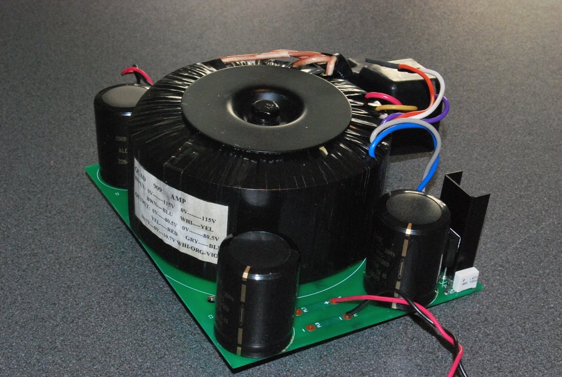
Description of the amplifiers, as bought on the second hand market:

-Serial number: 005 095; one amp board with power transistors MJ15003, the other with MJ15024; furthermore capacitor C9 and C11 were not foreseen by factory , drivers “40872 – no brand”
-Serial number: 005 097, original power transistors RCA 17556, drivers RCA40872
Both of them had power amp boards 12828/7 (not the later -8), the original power-supply elco’s, XLR inputs and LS outputs; there were no output limiters or input transformers; XLR pins 1 and 3 were bridged. In fairly mint state, with scratches; used in a tennis club during 20 years, but apparently no heavy use (no blackened components).

General (my) philosophy:

- Some people prefer to keep everything in ‘original’ state (in order to keep a decent market price for the private museum lovers), and/or only repair what is faulty; to the contrary, I have a tendency to upgrade components/circuit whenever it will have a positive impact on overall sound quality, and will change even the ‘look’ if it improves technical functionalities (also, it gives a personal exclusive touch!).

- The conversion to mono-blocking was in my configuration mandatory: I use one power amplifier for one loudspeaker; the challenge was to see if those Quads would be competitive with the legendary Studer A68’s or ACCUPHASE M100…

- I am a music/audio-lover, not a qualified technician (with some basic technical knowledge acquired during the years); so, many thanks to the prompt, no nonsense advices of Stefaan (by the way, he also sells the components !) and Joost from DaDa Electronics, and especially Louis (audio technician of Microware Solutions workshop in Dendermonde, disposing of a scope and frequency generator); I am sure, especially for the latter, that it wasn’t always easy to satisfy all my inquiries, indeed “paradise” –not even the technical- isn’t to be easily found on earth !!

- Never underestimate the complexity of things; Mister Peter Walker’s principle ‘Keep it simple’ was not always followed up by his production people !(different boards, omissions, many versions/changes in the 500 Series); by the way, this project was a piece of cake compared to the revision of the integrated ‘MARANTZ PM94’…don’t even think buying this nightmare !!

The upgrading of the amplifiers

First of all: I applied strictly the content of Joost’s blog (just go to the blog ‘520f’, nice pictures). Very clear on ‘what to do’ issues, except details for mono conversion. This was our main reference.

Additional:


- I removed the existing XLR LS connections – what an unpractical connection!- and replaced by WBT looking terminals. Of course, the old oxidized input XLR is replaced by a new Neutrik.

- A SOWTER 3575 input transformer was installed (in order to match the incoming balanced line from my preamplifier to an asymmetrical signal; although Joost didn’t like the idea, I installed after the transformer a cinch (RCA) connector (flexible use in other audio installations); a switch to isolate the transformer in the circuit was necessary: if not, a square wave of 30 Hz input signal looks awful because the RCA input line is somewhat influenced by the transformer…NB: this transformer was optionally installed by Quad in the eighties and is still produced.

- Substitution of the power transistors MJ15024 by MJ15003 for conformity.

- Replacement of internal signal cabling by a multi-wired core, shield, both Teflon insulated; they are not very flexible, nor easily stripped.

- Replacement of all small 0.1 ohm resistors R32 (one of them was faulty; the rest didn’t ‘look’ in good shape, metal film 1% on all power-amp boards.

- Original opamp: Stefaan is right, although recommended by several discussions on websites, a replacement of the original isn’t necessary (because NOT in the signal path)

- Mono conversion: look at the components that Stefaan added to the blog of Joost; as the potmeter in the Quads aren’t sufficiently accurate for ‘trimming’ the output voltage between the two channels, a dedicated 5Kohm was installed and one of the original was put on retirement. Now, this resulted in an acceptable imbalance of about 20 mV between the power-outputs. Placement of the 2 loudspeaker connections, with Dale resistors.

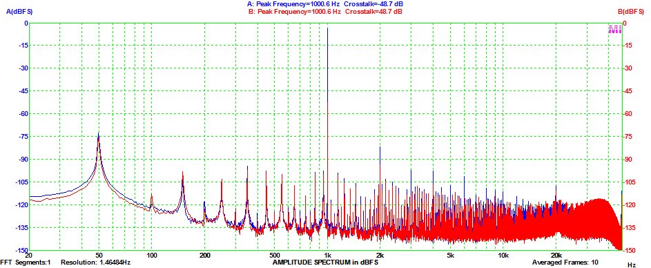
Some measurements: (input of 230 Volt mains with a variac):

- Peak to peak voltage of about 90 Volt, resulting in a 32 Volt RMS or about 130 Watt (before clipping) power on a LS load of 8 ohm. The old RCA transistors gave even a couple of volts more!
- On a power supply board, an imbalance between H+ and H- of some volts: 51/54 Volt with no load (don’t worry says Stefaan…); the other unit approached the total 110 Volt of supply voltage.
- Very nice scope analysis of 15 kHz and 30 Hz sinus signals.

- The volume-potmeter indicator was somewhat calibrated to the notional ‘0db inscription’ with a signal of 1 kHz / 0,775 V and ‘just’ before clipping.

- On one of the mono-amplifiers I had an audible (ear against loudspeaker; nothing at 0,5 meter distance) hum…Spent a lot of time on efforts to cure it… a headache (not the elco’s but: mains transformer, input transformer, cabling, earth loop, ??!). Finally, back to the basics: I found the bad guy, the R40 was burnt!! Replaced with 1 watt dissipation type.
Nb you’ll find on diy websites many complaints about ‘noise’ from these amplifiers; they refer mostly to the standard xlr connector, where you have to connect the pins ‘earth’ and ‘cold’ signal ,with an asymmetrical signal input.

-Some further possibilities:

*This is a Professional amplifier, but surprisingly without a ‘standard’ overload or ‘clipping’ indicator. An omission, Mister Walker? I found a reliable circuit description – look at http://sound.westhost.com/project23.htm - based on a drop in the supply voltage when reaching high output levels. I think that Joost won’t like this ‘rape’ of the 520 front… I still hesitate, but I use to run high output levels and my preamplifier can deliver much more than 1 volt on dynamic cd’s! Beware: “clipping” is a complex subject!!

* Driver replacement by MJE 15031(don’t expect huge improvements)

Now, how does it sound?? "The proof of the pudding is in the eating"

After ten hours of listening: no disappointment. YES,.. they sound very dynamic, neutral, punch, very good lower bass, monitor like…’richer in details’ than my modified 405 II, perhaps lacking a bit the ‘velvet’ sound on voices/piano.
I keep them, for sure….together with Studer and Accuphase! Worthwhile!!!
Nb listening on loudspeakers Tannoy Kensington, alternate : Sonus Faber Amati (both of them very ‘musical’).

Stefan Vertongen


Comments by Joost: DaDa Electronics

First of all: we are very pleased with customers like Stefan. They try something different and are willing to share there experience with us and other Quad-fans.

The 520 has no voltage output limiter or indicator, that is correct but it is safegaurded by a strict current limiter and a thermal protection. Which simply swithes of the amplifier when it gets too hot.

Stefan mentioned "Pro" use and the omission of a clipping indicator. In most cases the power amp in pro use is out of sight, on stage with the loadspeakers, while the mixing desk is in the public area. So: set the levels right and use the clipping indicator on the mixing desk.

I will make a separate article about the monoblocking issues and the extra resistors needed.

I don't like input transformers, if you can avoid them: do it. But in the setting of Stefan they are needed. Quad used the Sowter's but replaced them by there own opamp-based input modules in later versions.

I keep the equipment as orignal as possible, but I understand the pragmatism behind Stefan's conversions.

Joost

Wednesday, August 25, 2010

Measuring distortion with software


The case with the “Chinese” Quad 909 was the first occasion we worked with a software based distortion analyzer.

I used to work with a Sound Technology 1710A. The unit needs calibration and some repair; I have sent mails to ST, but no response until now. Just a calibration is a staggering 995 dollar or so, ex P&P, if they accept the work. Then I realized that even if they were willing to repair the unit, the performance will not be good enough to measure modern or modified vintage equipment. So we moved on.

Distortion analyzers like the ST are based on wideband AC RMS meters. First you measure the output signal of the amplifier under test, then you remove the test tone and measure the residue. Eventually you can calculate the distortion. This is off course distortion including noise.

The software distortion analyzers are based on a spectrum analyzer program and analog-to-digital and digital-to-analog converters. This type of analyzers measures the individual frequency components, the rest is “only” calculation!

Spectrum analyzers existed in the pre digital days, but they where very expensive.

The theory behind this is the fact that every repeating signal can be decomposed in so called harmonics and the basic frequency component. To measure amplifiers you also need a signal generator and an oscilloscope in (preferable) one software package. I started with a freeware solution from Sillanum Soft and the standard sound card in my PC. The results were very promising. The next phase was a high quality, 24 bit, 192 KHz sampling rate, low distortion, soundcard with balanced outputs (ESI Juli@). The results were more than ok. Because the Sillanum Soft package only has the basic functionality, I bought a package from Virtins Technology and built a proper brake out box with volume controls, a variety of connections and a possibility to connect load resistors and other lab equipment. To get more speed (calculation power) from the PC, I also installed a 64 bit operating system (dual boot option).

From the website of Audio Precision, a high end distortion analyzer manufacturer, I downloaded two very useful documents. The Audio Measurement Handbook and a large document titled "How to write and read audio specifications". By reading and digesting the last document you will find that most specifications of commercial audio equipment are not complete and meaningless in most cases! Even our Quad heroes wrote those kind of specs!

A practical case: measuring a Dada Electronics revised Quad 303

See the specifications in the picture. First I checked the distortion. Quad measured at a strange frequency of 700Hz. Also the term “unrestricted bandwidth” is undefined. What does ”up to 45 watt” mean in real terms of voltage and watts? My own settings: 1 KHz test signal, bandwidth: 20Hz to 20 KHz and 45 watt in 8 ohm loads, both channels driven and loaded. As you can see the specification of 0.03% is easily met. If you remove or lower the load the result is spectacular. Very low distortion indeed.

The next measurement was the crosstalk. Quad did not specify the output parameters. As you can see, with the channels loaded with 8 ohm and the power at 45 watts, the channel separation is below modern standards. Only good enough for vinyl replay or FM broadcasts. If you remove or decrease the load, it is ok.
So there are people who say the 303 is the best Quad amplifier ever made. We don’t agree if you use the 303 with modern digital source material combined with high volume settings. This is one of the reasons we advise to monoblock a 303 or use it in a bi-amp application per channel. The load dependent cross talk can influence the stereo soundstage.

The next myth: high bias current

In the Quad service manual it is stated that the DC bias current of the power transistors must be between 10mA and 5mA. A popular “mod” is increasing the current to 35mA and in some cases even higher. Well, in real life the distortion is only 0.05% at a bias current of 0.5mA. At 5mA it is 0.01% and will not get lower at higher bias currents. Also the spectrum analyzer will not give a better (cleaner) picture at high levels of bias current. So Quad was (is) right! For practical reasons, stability of the circuit, 10mA is a good value for the bias current.

Joost Plugge

Virtins Technology
Sillanumsoft
ESI
Audio Precision

Labels: , , , ,

Sunday, August 08, 2010

Improving a new Quad 909

One of our French customers, who is working in professional audio, bought a new Quad 909 to drive his Tannoy studio-monitors.


He has always used Quad 303 monoblocks with Dada High-end boards and was very pleased with the result so, as he needed more power for another project he bought a 909.


The Tannoys are very sensitive and transparent (as studio monitors should be). When he connected the 909 he heard a hiss and distortion in the mid-tones.He brought back the amplifier to the reseller and it was tested by Quad. They said everything was working within specifications so there was nothing they could do.


So he sent the amplifier to Dada Antwerp and asked us to find the reason of the problem and to see what we can do about it.


Joost and me took an afternoon to do some tests with Virtins Multi-instrument Audio analyser and the other lab-equipment.


First we did a listening-test. The sound was rather "harsh" and "metalic" compared to other (revised) Quads.


We measured a Total Harmonic Distortion of 0,8854% (!) and a Signal-to-Noise Ratio of 81,4dB at full power with 8 Ohm load. The total power before clipping was 120W RMS. Very bad figures for a high-end amplifier... And much worse than the "classical" 606 the 909 is based on.


We decided to take the amplifier apart and to concentrate on 3 possible sources of distortion:


  • The power-supply

  • The amplifier-boards

  • The input-board for the Quadlink

The power-supply board is the "classical" board known from the 606-II and the 707 with a Toroïdal transformer and 4x 15000µF capacitors in a dual-mono design. Only, the original BHC Aerovox capacitors have been replaced by Chinese CapXon capacitors.


We took them out to test them with the Hameg LCR meter.


The BHC Aerovox was the ALP22A 63Volt, the CapXon has no type-indication, it is a plug-in two pin 80Volt 105° type.


We measured the capacitance at 100Hz, 1KHz, 10KHz and 25KHz with a 1V DC bias voltage. Both were within specifications (15mF or more) up to 1KHz. At higher frequencies the BHC scores better with 3x higher capacitance, for example 1100µF at 10KHz instead of 300µF for the CapXon.


The measured internal resistance is about the same and around 10mR at 1KHz.


This leads us to the conclusion that both capacitors are very comparable with a slight advantage for the BHC specifically in the higher frequencies. Of course this test doesn't say anything about the ageing of the capacitors after several hours of usage. The BHC has an excellent reputation for ageing. We decide to replace the 4 CapXon in the power-supply with BHC Aerovox.


Then we take a look at the amplifier boards. We replace the low-cost capacitors as usual, the electrolytes with Nichicon, the range between 1nF and 1µF with Wima MKS and the range below 1nF with Silvered Mica.


We also recalculated the bridge and used the exact values for the bridge components. Joost will comment on this later.


We connect the driver-boards to the power-supply. Now we measure a THD of 0,025% and a S/N Ratio of 87dB which is a lot better yet. A listening test gives the rich and transparent sound we are used to with Quad amplifiers.


Finally we take a look at the input-board that also contains the switch-on delay and the symmetric -> asymmetric conversion for the Quadlink.


The asymmetric signal from the RCA-inputs also passes through the output-stages of the preamplifier and again we find some low-cost capacitors on board. At a low input voltage the THD of the board is 0,003% but increasing the input-voltage increases the THD of the board. Around 10V we have 0,4% THD.


As the customer won't use the Quadlink we decide to remove the board from the signal-line and to connect the RCA-inputs directly to the amplifier-boards like in the 606.


The conclusion is that every detail has it's importance for the final sound-quality, specially the quality of the components and that it is best to avoid the Quadlink if you don't need it.


Stefaan


Practical: Component list


The 909 PCB is a thhrough-metalised PCB. You should use a good desoldering-pump or a desoldering-station to remove the old components.


For soldering on the PCB's only use lead-free solder. Tin/lead solder won't mix with the solder on the board.


You can click on the components below to go directly to the Webshop for ordering or for seeing more technical information or price and availability.


This way we have replaced all electrolyte capacitors with the best quality and we have adapted the bridge to the optimum value.


The specifications of the 909 transformer are: 2x 80,5 Volt 500VA


Measurement of a 606 MKII (my own) as a reference:


Vout is 32.2 V, no load, left and right channel:


THD 0.0009 and 0.0010

IM Din 0.0045 and 0.0041


Vout is 32.2 V, load is 8 Ohm:


THD 0.0129 and 0.0059

IM Din 0.0342 and 0.04


So the left channel is out of spec, THD should be lower than 0.01 some work ahead!


Joost Plugge